Light-homogenized rod and illuminating system

A technology of uniform light rod and rod body, applied in the field of optics, can solve the problems of increased difficulty, increased volume and length of the illumination optical system, and achieves the effect of simplifying adjustment difficulty, enhancing the uniform light effect, and shortening the length.

Inactive Publication Date: 2019-06-28
GEOPTICS SEQUENCING EQUIP CO LTD
View PDF8 Cites 4 Cited by
  • Summary
  • Abstract
  • Description
  • Claims
  • Application Information

AI Technical Summary

Problems solved by technology

[0007] In order to enhance the uniformity of illumination and meet the demand for uniform illumination of a larger field of view optical system, the volume of the illumination optical system will increase by increasing the uniformity rod, especially the length will increase rapidly, which will lead to an increase in the volume of the entire product and cost increase
[0008] The combination of dodging rods and microlens arrays makes the installation and adjustment of the illumination optical system more complicated and difficult

Method used


Image

  • Light-homogenized rod and illuminating system
  • Light-homogenized rod and illuminating system
  • Light-homogenized rod and illuminating system

Examples


Embodiment 1

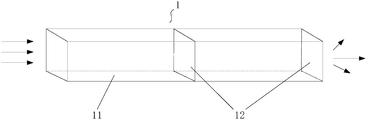
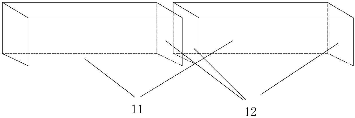
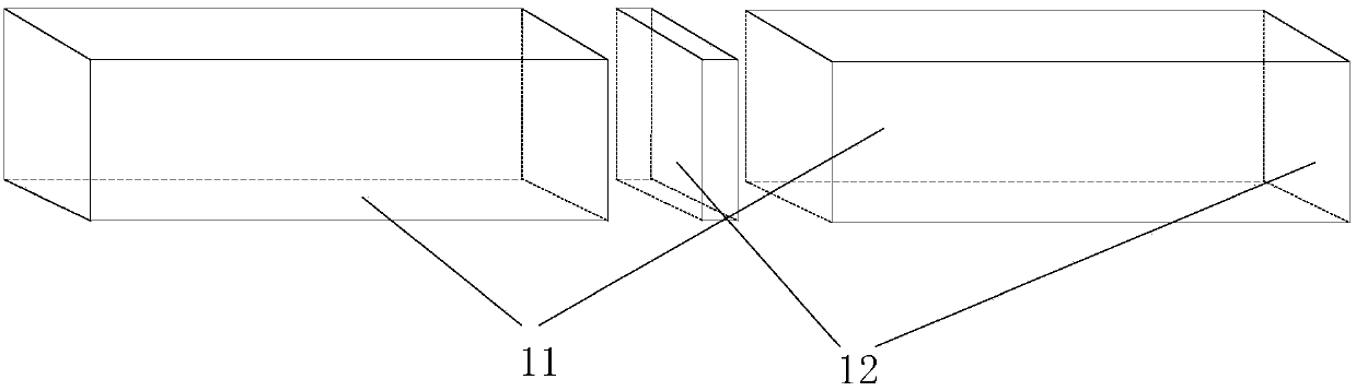
[0031] This embodiment provides a dodging rod with a diffractive layer. The dodging rod is a solid rod body or a hollow rod body whose inner wall is coated with a reflective film. The diffractive layer includes one or more, and the diffractive layer is arranged on the middle part or the end face of the dodging rod, or is arranged on the middle part and the end face of the dodging rod at the same time, preferably, the end face provided with the diffractive layer is the light emitting surface of the dodging rod. There is a diffraction pattern on the diffraction layer, and the diffraction pattern is mainly a diffraction hole, which diffracts light at different incident angles through multiple diffraction holes, which improves the uniformity of the light emitted by the homogenizing rod, and at the same time makes the energy distribution of the laser beam tend to be uniform , no longer tends to a Gaussian distribution. The diffraction layer makes the laser diffract during the tran...

Embodiment 2

[0042] This embodiment provides a lighting system including the light uniform rod of the first embodiment above. The lighting system also includes optical components such as a light source and a lighting mirror group. The lighting system with the above light uniform rod can emit better uniform light. In this embodiment, as Figure 8 The illustrated lighting system is described as an example. In other embodiments, the lighting system may include other optical components on the basis of the above-mentioned dodging rod 1 .

[0043] Such as Figure 8 As shown, the lighting system of this embodiment includes a light source 2 , a homogenizing rod 1 , a condenser lens 3 , an illuminating lens group 4 and a microscope objective lens 5 from top to bottom.

[0044]The light source 2 includes a laser and an optical fiber connected thereto, and the laser emits laser light through the optical fiber. The light source 2 can emit laser light of one wavelength or multiple wavelengths, and th...


PUM


Abstract

The present invention discloses a light-homogenized rod. The internal portion or/and end face of the light-homogenized rod are provided with a diffraction layer, and the diffraction layer is providedwith a diffraction pattern. The internal portion or/and the end face of the light-homogenized rod are provided with the diffraction layer comprising the diffraction pattern, the diffraction layer enhances the light homogenizing effect to obtain better homogenized light in a condition without increasing the light-homogenized rod or increasing a micro-lens array so as to facilitate reduction of thelength of the large visual field illuminating system, simplify the regulation difficulty of the optical path, and therefore, the light-homogenized rod and the illuminating system are especially suitable for the large visual field illuminating/projection optical system.

Description

technical field [0001] The invention relates to the field of optical technology, in particular to a uniform light rod and an illumination system. Background technique [0002] Homogenization rods, also known as light rods and light pipes, are usually used to homogenize light beams. According to different structural forms, dodging rods can be divided into solid rods and hollow rods. In laser projection systems, microscopic lighting, gene sequencing equipment lighting, and lithography machine lighting systems, the dodging rod is used as a dodging device to achieve good lighting uniformity. [0003] The principle of homogenization by the dodging rod is: to reflect the light incident to the dodging rod at a certain divergence angle multiple times to make the beam distribution uniform, and then realize the dodging effect of the dodging rod. [0004] In applications such as projection lighting systems and microscopic imaging lighting systems, the light source usually uses a high...

Claims


Application Information

Patent Timeline
Patent Type & Authority Applications(China)
IPC IPC(8): G03B21/20G02B27/09
Inventor 陈新东乔彦峰
Owner GEOPTICS SEQUENCING EQUIP CO LTD
Why Eureka
Try Eureka