A fast phase commutation method for low-voltage distribution network based on magnetic latching relay

A technology for magnetic latching relays and low-voltage distribution networks. It is applied in relays, circuits, and electric switches. It can solve problems such as arcing, affecting the normal operation and life of relays, and affecting the normal power consumption of loads.

Active Publication Date: 2021-07-06
CENT SOUTH UNIV
View PDF3 Cites 0 Cited by
  • Summary
  • Abstract
  • Description
  • Claims
  • Application Information

AI Technical Summary

Problems solved by technology

However, during the load commutation process performed by the terminal commutation switch, it is very easy to affect the normal power consumption of the load. This paper studies the new method of fast commutation in low-voltage distribution network to solve this problem.
[0003] The previous commutation switch mainly composed of relays has a simple drive circuit, strong overcurrent and overvoltage capacity, and strong anti-interference ability. However, the traditional control method takes a long commutation time, exceeding 20ms, which affects electrical equipment. The continuous power supply, and the relay immediately performs the breaking task after receiving the switching command. At this time, it is very likely that the voltage or current passing through the relay is at the maximum value, and the arcing phenomenon is likely to occur, which does not meet the AC requirements. The principle of zero-crossing switching (refers to the principle of putting into the circuit and cutting out the circuit when the AC voltage and current are just at the zero point), which will affect the normal operation and life of the relay, and more serious consequences may be due to the contact of the relay. Burning so that the relay cannot be disconnected, resulting in a short circuit between phases
Therefore, it is urgent to solve the problems of long commutation time and unsafe commutation of the commutation method based on magnetic latching relays.

Method used


Image

  • A fast phase commutation method for low-voltage distribution network based on magnetic latching relay
  • A fast phase commutation method for low-voltage distribution network based on magnetic latching relay
  • A fast phase commutation method for low-voltage distribution network based on magnetic latching relay

Examples


Embodiment Construction

[0045] The present invention will be further described in detail below in conjunction with the accompanying drawings and examples. The following examples are explanations of the present invention and the present invention is not limited to the following examples.

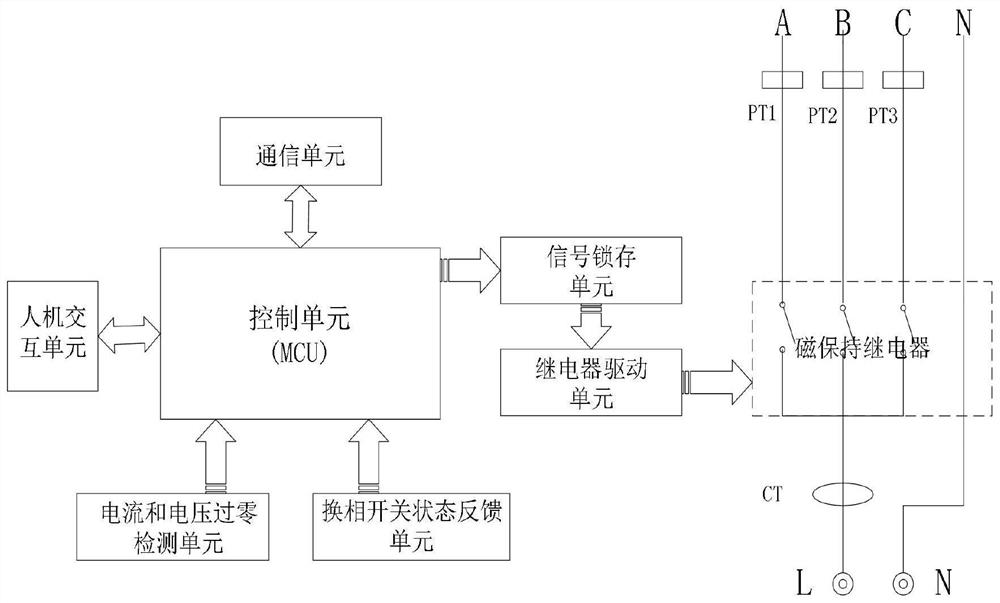
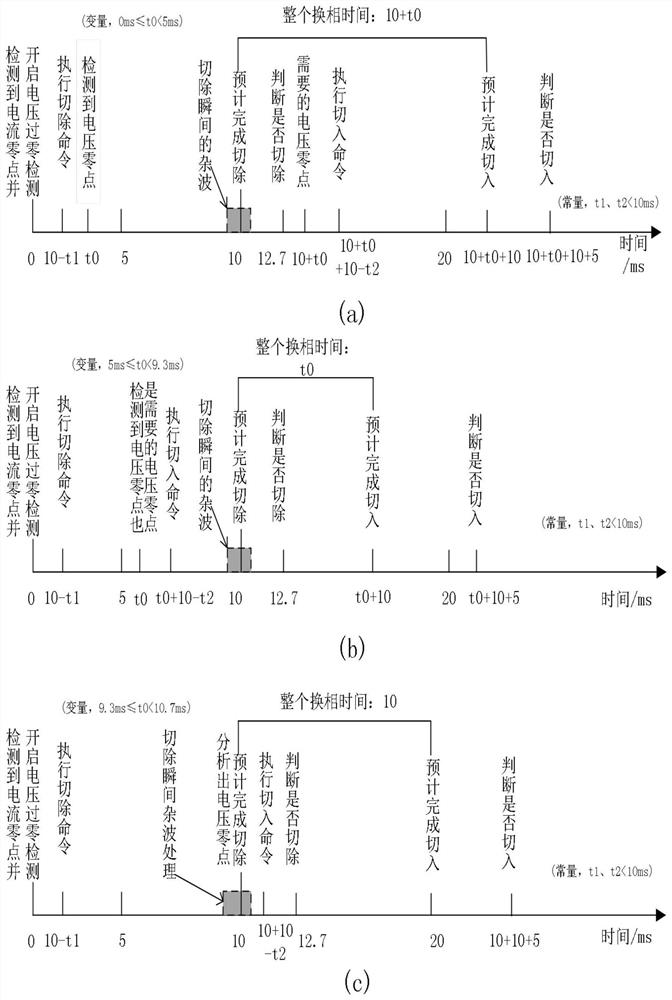
[0046] see Figure 1-Figure 3 , this example figure 1As shown, the system structure schematic diagram of a low-voltage distribution network commutation equipment provided by the embodiment of the present invention, the method of the present invention runs on the equipment, and the equipment includes a control unit (MCU), a relay drive unit, and a signal latch unit , current and voltage zero-crossing detection unit, human-computer interaction unit, communication unit and three magnetic latching relays.

[0047] Among them, the wires shown in A, B, and C are the output terminals of the three-phase circuit, and the positions of PT1, PT2, and PT3 on the three-phase circuits of A, B, and C are each equipped with a volta...


PUM


Abstract

The invention discloses a fast commutation method for a low-voltage distribution network based on a magnetic latching relay, using a magnetic latching relay as a commutation switch, combining the AC zero-crossing detection signal and the status feedback signal of the commutation switch, and using a sequential logic control algorithm to complete the load. Switching of phase sequence. By improving the control method of the magnetic latching relay, the present invention greatly shortens the power-off time during the commutation process, and the longest power-off time is about 15ms, which does not affect the normal power consumption of household user loads, and satisfies the principle of AC zero-crossing switching , the error is small, no arc will be generated, and the appropriate verification time is set by using the state feedback signal of the commutation switch to judge whether the cut-off and cut-in are successful, which can avoid short-circuit between phases and ensure the normal operation of the low-voltage distribution network .

Description

technical field [0001] The invention relates to the field of power system distribution network automation and control, in particular to a low-voltage distribution network fast phase commutation method based on a magnetic latching relay. Background technique [0002] my country's low-voltage distribution network mainly adopts a three-phase four-wire system. Ideally, the three-phase load is a balanced configuration. In fact, due to the access of high-power single-phase loads and differences in user habits of electricity, it is often easy to cause the end of the distribution network to The voltage is lower than the limit value, which aggravates the three-phase imbalance problem and greatly increases the power loss. The intelligent phase selection switch is the first recommended method to control the three-phase unbalance in the "Notice on Carrying out the Governance of Three-phase Load Unbalance in Distribution Areas" by the Ministry of Transport and Inspection of the State Grid...

Claims


Application Information

Patent Timeline
Patent Type & Authority Patents(China)
IPC IPC(8): H01H9/56H01H47/02H02J3/26
CPCY02E40/50
Inventor 宫飞丁家峰李新梅
Owner CENT SOUTH UNIV
Why Eureka
Try Eureka