Heat exchanger apparatus

A heat exchanger and equipment technology, applied in the field of cooling systems and heat exchanger equipment, can solve problems such as poor thermal conductivity, and achieve the effects of reducing flow resistance, optimizing flow rate and cooling efficiency, and improving evaporation rate

Pending Publication Date: 2019-06-28
UNIVERSITY OF HULL
View PDF5 Cites 1 Cited by
  • Summary
  • Abstract
  • Description
  • Claims
  • Application Information

AI Technical Summary

Problems solved by technology

This non-metallic material has poor thermal conductivity

Method used


Image

  • Heat exchanger apparatus
  • Heat exchanger apparatus
  • Heat exchanger apparatus

Examples


Embodiment Construction

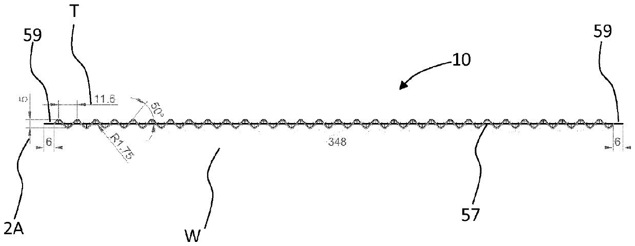
[0040] figure 1 A perspective side view, generally designated 10, of a heat exchanger lamella according to an embodiment of the present invention is shown. exist figure 1 In , the heat exchanger sheets are shown in their normal orientation in use. The heat exchanger sheets 10 are 5005 series aluminum. The heat exchanger foil 10 is corrugated in the upper region 14 . The 5005 series aluminum used to form the heat exchanger sheet 10 provides suitable ductility to form the corrugations and also provides the required thermal conductivity. The upper region 15 of the heat exchanger foil 10 is planar. The lower region 16 of the heat exchanger foil 10 is planar. It is also shown that the transition 17 from each of the upper region 15 and the lower region 16 to the corrugations is smooth. The heat exchanger foil 10 is 360 mm wide and 1000 mm long. The length of the corrugated area of ​​the heat exchanger foil 10 is 860 mm. The length of the planar region 16 is 115 mm and the le...


PUM

PropertyMeasurementUnit
lengthaaaaaaaaaa

Abstract

The invention relates to a heat exchanger apparatus comprising at least one metal sheet (10) (e.g. aluminium), and preferably a plurality in a stack. Each metal sheet (10) has a corrugated surface, with fabric covering at least a portion of one surface of the metal sheet to promote evaporation. A wetting agent (e.g. LiCl/Polyvinyl-Alcohol (PVA) solution) is provided in the fabric to promote wetting of the fabric, and also acts as an anti-microbial agent. The fabric preferably covers all of the corrugated surface, and two planar portions are provided above and below the corrugated surface respectively. In use, the heat exchanger apparatus is disposed with a long side vertical and the corrugated surface is disposed on a middle portion, the upper planar portion is contiguous with an air outlet, and/or the lower planar portion is contiguous with an air inlet. In a preferred embodiment, the corrugated surface has in cross-section a profile of a periodic waveform, wherein the peak-to-peak distance is 11.6 mm, the amplitude is 2.5 mm, and corrugations intersect the plane of the heat exchanger apparatus at an angle to that plane of 50 degrees. Also disclosed are a cooling system incorporating the heat exchanger apparatus and methods of operating the cooling system, involving intermittently operating a water supply system for the application of water to the fabric, and/or, recirculatingwater from a water sump using the water supply system.

Description

technical field [0001] The present invention relates to cooling systems relying on evaporative cooling, and more particularly to heat exchanger apparatus, cooling systems and methods of operation thereof. Background technique [0002] It is known to provide a dew point air conditioner comprising a flat plate heat exchanger with complex heat exchanger lamellae, fans, pumps, housing and controls. Known heat exchanger surfaces are generally left untreated, resulting in poor water distribution and insufficient wetting due to the effect of gravity on the water, especially in the horizontal direction. This results in poor heat transfer and mass transfer between the dry and wet channel air streams of the heat exchanger. In addition, due to poor water distribution and insufficient wetting, the amount of circulating water in the air conditioner causes the pump of the air conditioner to consume a lot of electricity. [0003] Known plate heat exchangers do not fully utilize the heat ...

Claims


Application Information

Patent Timeline
Patent Type & Authority Applications(China)
IPC IPC(8): F28F25/08F28C1/00F28D3/00F28F3/02
CPCF28D9/0093F28D9/04F28F3/06F28F3/08F28F3/14F28F21/00F28F2265/20F28F3/027F28F25/087F28C1/00F28D3/00F28F2245/02Y02B30/70F28C2001/006F28D3/04
Inventor 赵旭东徐鹏马小丽K.芬西李俊明
Owner UNIVERSITY OF HULL
Why Eureka
Try Eureka