
Fracturing and sand prevention pipe column and fracturing and sand prevention method

A technology of fracturing sand control and sand control screen, which is applied in the direction of earthwork drilling, production fluid, wellbore/well components, etc., and can solve the problems such as failure to achieve sand control effect, failure of the screen to be lowered, and formation well wall collapse. Achieve the effects of avoiding formation well wall collapse, easy control and reduced completion cost

Pending Publication Date: 2019-07-02
PETROCHINA CO LTD
View PDF0 Cites 3 Cited by
  • Summary
  • Abstract
  • Description
  • Claims
  • Application Information

AI Technical Summary

Problems solved by technology

However, in the prior art, when the fracturing fluid is flowed back after the fracturing is completed, there is often the problem of fracturing sand returning back, which not only has a poor sand filling effect, but also brings many difficulties to the later sand washing
At the same time, due to the phenomenon of sand production in the heterogeneous loose sandstone itself, after fracturing, the secondary completion is directly carried out and the sand control screen is inserted. Repeated tripping operations will cause the bottom hole pressure to be lower than the formation pressure, resulting in the collapse of the formation well wall, which in turn leads to The screen cannot be lowered into the designated position, and the sand control effect cannot be achieved

Method used


Image

  • Fracturing and sand prevention pipe column and fracturing and sand prevention method
  • Fracturing and sand prevention pipe column and fracturing and sand prevention method
  • Fracturing and sand prevention pipe column and fracturing and sand prevention method

Examples


Embodiment Construction

[0045] In order to make the purpose, technical solutions and advantages of the present invention clearer, the technical solutions in the present invention will be clearly and completely described below in conjunction with the accompanying drawings in the present invention. Obviously, the described embodiments are part of the embodiments of the present invention , but not all examples. Based on the embodiments of the present invention, all other embodiments obtained by persons of ordinary skill in the art without creative efforts fall within the protection scope of the present invention.

[0046] In describing the present invention, it is to be understood that the terms "centre", "length", "width", "thickness", "top", "bottom", "upper", "lower", " "Left", "right", "front", "rear", "vertical", "horizontal", "inner", "outer", "axial", "circumferential", etc. indicate the orientation or positional relationship based on the drawings The orientations or positional relationships sho...


PUM


Abstract

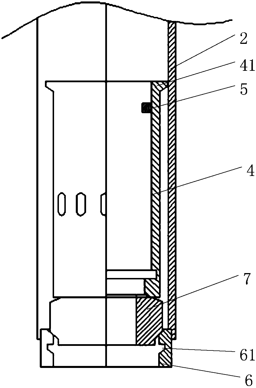
The invention provides a fracturing and sand prevention pipe column and a fracturing and sand prevention method. The fracturing and sand prevention pipe column comprises a casing pipe and an oil pipearranged in the casing pipe, an annular space is formed between the casing pipe and the oil pipe, a fracturing packer is arranged on the oil pipe, a ball seat and a sand prevention sieve pipe are arranged in the bottom end of the oil pipe in a sleeved mode, the ball seat is in threaded connection with the upper part of the sand prevention sieve pipe, the bottom end of the oil pipe is connected with a limiting device, the limiting device is located on the lower part of the sand prevention sieve pipe, and the length of the sand prevention sieve pipe is greater than the thickness of a reservoir by 20 to 30 meters; a female buckle is arranged at the top end of the sand prevention sieve pipe, and a limiting groove is formed in the limiting device; when a soluble ball is put to strike the ball seat, the ball seat drives the sand prevention sieve pipe to move downwards until the female buckle is clamped in the limiting groove; and after the sand prevention sieve pipe is in place, still standing is conducted for 48 hours, and the soluble ball is dissolved. According to the fracturing and sand prevention pipe column, under the situation of not conducting secondary well completion, it can beensured that stratum sand and fracturing sand do not flow back from a stratum, and fracturing and sand prevention is integrated.

Description

technical field [0001] The invention relates to the technical field of production and completion of oil and gas wells in oil fields, in particular to a fracturing sand control string and a method. Background technique [0002] In the field of petroleum exploration, especially for the exploitation of heterogeneous cemented unconsolidated sandstone reservoirs, it is often necessary to cooperate with fracturing operations to form deep-penetrating, high-conductivity fractures in the reservoir to increase oil well production. At the same time, sand production in oil wells is a common problem in the development of unconsolidated sandstone reservoirs. Sand production will cause a series of hazards such as sand buried oil layers, equipment corrosion, and well wall collapse, directly affecting the productivity and output of oil wells. [0003] In the prior art, a large amount of quartz sand or ceramsite needs to be filled in the formation during fracturing, and after fracturing, sand...

Claims


Application Information

Patent Timeline
Patent Type & Authority Applications(China)
IPC IPC(8): E21B43/26E21B43/08
CPCE21B43/26E21B43/086
Inventor 白晓飞孟祥娟陈德飞贺梦琦彭永洪卢培华任利华曹献平
Owner PETROCHINA CO LTD
Learn More