Supercharge Your Innovation With Domain-Expert AI Agents!

Centralized cold source refrigeration circulation system

A circulation system and centralized technology, applied in refrigerators, air-conditioning systems, refrigeration components, etc., can solve the problems of low utilization efficiency, high power consumption, and high inlet air temperature of the condenser, so as to avoid the heat island effect and improve the annual Energy efficiency ratio, the effect of reducing energy consumption

Pending Publication Date: 2019-07-02
NANJING CANATAL DATA CENT ENVIRONMENTAL TECH CO LTD
View PDF0 Cites 2 Cited by
  • Summary
  • Abstract
  • Description
  • Claims
  • Application Information

AI Technical Summary

Problems solved by technology

Among them, the air-cooled refrigeration system and the water-cooled refrigeration system use compressors for refrigeration all the year round, and the system consumes a lot of energy and electricity.
There is a hidden danger of water entering the machine room in the chilled water refrigeration system
The fluorine pump double-cycle refrigeration system uses natural cold sources, but for areas with high outdoor temperatures in the south, the utilization efficiency is low
Moreover, for the occasions where the condenser is relatively concentrated and heat island effect is easily generated, although the outdoor temperature is low, due to the heat island effect, the inlet air temperature of the condenser is high; the actual use time of the fluorine pump is relatively short

Method used


Image

  • Centralized cold source refrigeration circulation system
  • Centralized cold source refrigeration circulation system
  • Centralized cold source refrigeration circulation system

Examples


Embodiment Construction

[0018] The present invention will be described in further detail below in conjunction with the accompanying drawings and specific embodiments.

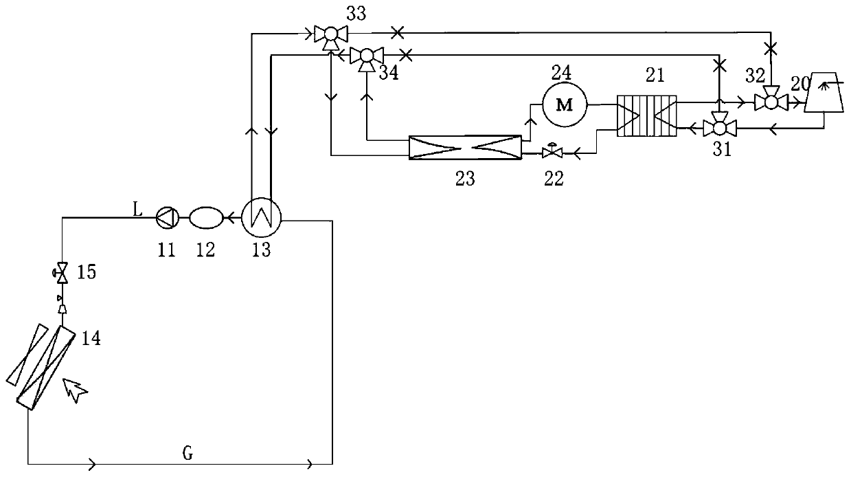
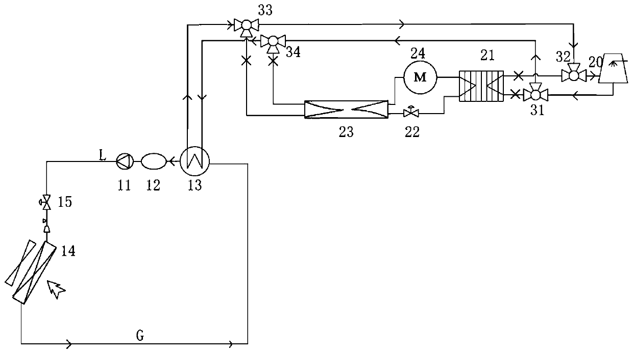
[0019] like figure 1 As shown, a centralized cold source refrigeration cycle system disclosed in the embodiment of the present invention is mainly composed of a direct refrigeration unit and a centralized cold source unit. The main components of the direct refrigeration unit include refrigerant pump 11, liquid receiver 12, water-cooled condenser A 13, evaporator 14, and throttling element A 15, and the main components of the centralized cold source unit include cooling tower 20 and water-cooled heat exchanger B 21. Throttling element B 22, water-fluorine heat exchanger 23, high-efficiency inverter compressor 24, and three-way valve I / II / III / IV (31 / 32 / 33 / 34). In the direct refrigeration unit, the refrigerant pump 11, the liquid receiver 12, the water-cooled condenser A 13, the evaporator 14, and the throttling element A15 are connecte...


PUM


Abstract

The invention discloses a centralized cold source refrigeration circulation system. The centralized cold source refrigeration circulation system comprises a direct refrigeration unit and a centralizedcold source unit; the direct refrigeration unit comprises a refrigerant pump, a liquid storage device, a water-cooled condenser A, an evaporator and a throttling element A; the centralized cold source unit comprises a cooling tower, a water-cooled condenser B, a throttling element B, a water fluorine heat exchanger, a compressor, a three-way valve I, a three-way valve II, a three-way valve III, and a three-way valve IV; the water-cooled condenser B, the throttling element B, the water fluorine heat exchanger and the compressor are sequentially connected to constitute a refrigerant circulationloop; and the three-way valve I and the three-way valve II are arranged on the pipeline where the water-cooled condenser B is connected with the cooling tower, the three-way valve III and the three-way valve IV are arranged on the pipeline where the water-cooled condenser A is connected with the water fluorine heat exchanger, the three-way valve I is connected with the three-way valve IV, and thethree-way valve II is connected with the three-way valve III. According to the centralized cold source refrigeration circulation system, the outdoor centralized cold source unit provides cold resources for the system, the indoor compressor is omitted, energy consumption of the unit is reduced, the outdoor natural cold sources can be fully utilized, the annual energy efficiency ratio of the unit is increased, and thus the energy saving purpose is achieved.

Description

technical field [0001] The invention belongs to the technical field of refrigeration, and in particular relates to a centralized cold source refrigeration cycle system. Background technique [0002] With the rapid development of my country's communication industry and the widespread use of 4G and even 5G, communication base stations and computer rooms have been developed on a large scale, and the energy consumption problem of communication companies has become more and more prominent. According to statistics, the power consumption of air conditioners in computer rooms accounts for more than 40% of the total electricity consumption in computer rooms. Due to the particularity of the air-conditioning environment in the computer room, the computer room needs to be refrigerated 365 days a year. The natural cold air outside the computer room is a huge natural cooling source during part of the year. If it can be used reasonably, there will be a lot of room for energy saving in the...

Claims


Application Information

Patent Timeline
IPC IPC(8): F24F5/00F24F11/65F24F11/84F24F13/30F25B1/00F25B39/04F25B41/04F25B49/02F25B41/20
CPCF24F5/001F24F11/65F24F11/84F24F13/30F25B1/00F25B39/04F25B49/02F25B41/20
Inventor 程姗许海进刘静王成洁
Owner NANJING CANATAL DATA CENT ENVIRONMENTAL TECH CO LTD
Features
  • R&D
  • Intellectual Property
  • Life Sciences
  • Materials
  • Tech Scout
  • Unparalleled Data Quality
  • Higher Quality Content
  • 60% Fewer Hallucinations
Learn More