An explosive foil integrated chip based on low temperature co-fired ceramics and its preparation process

A technology of low-temperature co-fired ceramics and integrated chips, which is applied in blasting barrels, offensive equipment, weapon accessories, etc., can solve the problems of low energy utilization efficiency of explosive foil detonator units, difficulty in miniaturization, and unreliable functions, and achieve energy utilization The effect of increasing the efficiency, improving the consistency of the product, and reducing the ignition energy

Active Publication Date: 2022-02-18
NANJING UNIV OF SCI & TECH
View PDF5 Cites 0 Cited by
  • Summary
  • Abstract
  • Description
  • Claims
  • Application Information

AI Technical Summary

Problems solved by technology

Manual or mechanical alignment and installation methods are prone to misalignment, which makes the energy utilization efficiency of the explosive foil detonator unit low and the effect is unreliable
In addition, the traditional explosive foil detonator unit has a large structural volume and high ignition energy, and it is difficult to achieve miniaturization

Method used


Image

  • An explosive foil integrated chip based on low temperature co-fired ceramics and its preparation process
  • An explosive foil integrated chip based on low temperature co-fired ceramics and its preparation process
  • An explosive foil integrated chip based on low temperature co-fired ceramics and its preparation process

Examples


Embodiment

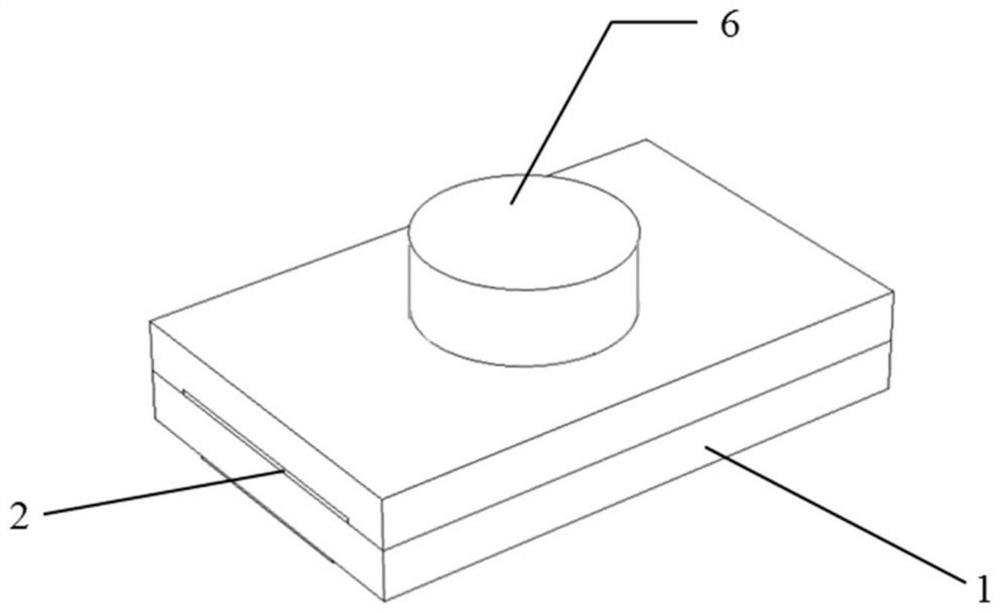
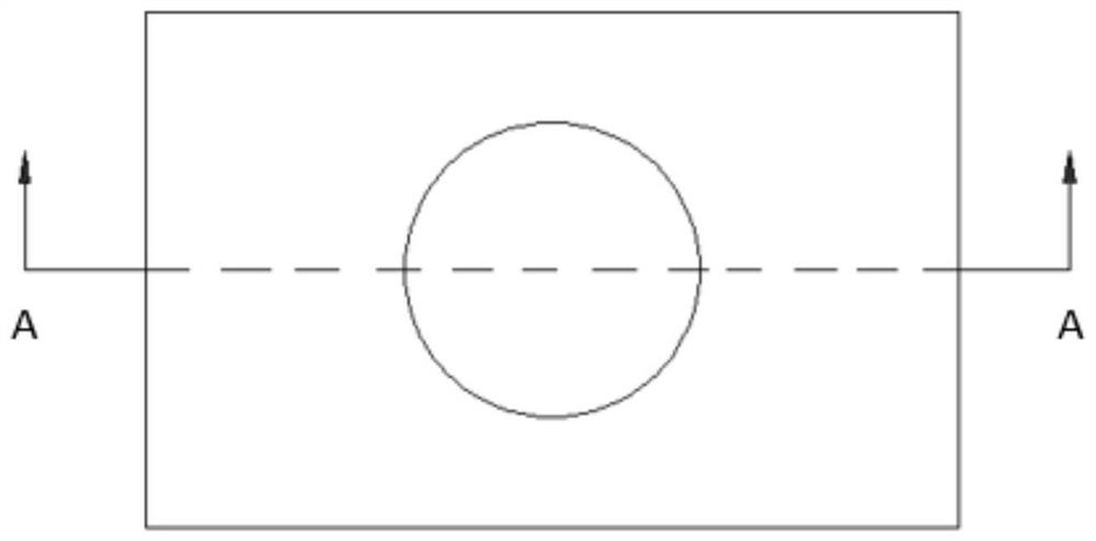
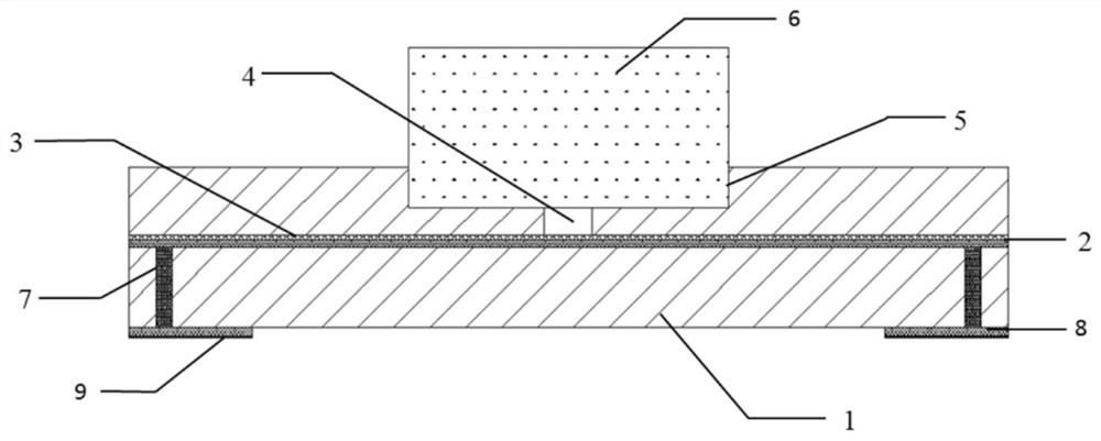
[0047] In this embodiment, an explosive foil detonator is designed on the basis of the explosive foil integrated chip unit, combining figure 1 to Figure 5 , the explosive foil integrated chip unit includes a ceramic substrate 1, a metal Au layer 2, a Parylene C layer 3-a, a metal W-Ti / Cu layer 3-b, an acceleration chamber 4, a charge tank 5 and an explosive column 6, In addition, it also includes metal via holes 7-a in the ceramic substrate 1, paste 7-b, pad area 8 on the back and Pd / Ag layer 9, etc. to facilitate connection with other parts. The ceramic substrate 1 is used as the back plate in the explosive foil integrated chip, and its length, width and height are 11mm×7mm×1mm respectively. The metal Au layer 2 is placed on the ceramic substrate 1 with a thickness of 6-10 μm. The metal Au layer 2 includes bridge Area 2-a, transition area 2-b, and conduction band 2-c. The bridge area 2-a is the part with the smallest cross-sectional area in the metal Au layer 2, and its ar...


PUM

PropertyMeasurementUnit
thicknessaaaaaaaaaa

Abstract

The invention discloses an explosive foil integrated chip based on low-temperature co-fired ceramics and a preparation process thereof. Explosive foil integrated chip includes: ceramic substrate, metal layer, flyer layer, acceleration chamber, charge tank and explosive column, and also includes metal vias in the ceramic substrate, paste, and pad area on the back and Pd / A structure such as an Ag layer that facilitates connection with other parts. The ceramic substrate is used as a reflective backplane in the integrated chip; the metal layer includes three parts: bridge area, transition area and conduction band; the flyer layer includes ceramic flyer, Parylene C / W‑Ti / Cu composite flyer; the function of the acceleration chamber is to provide acceleration space for the flyer; the charging groove provides precise positioning for the placement of the explosive column. Compared with the prior art, the present invention has the advantages of using low-temperature co-fired ceramic technology to make the explosive foil detonator more integrated and smaller in volume, which can realize mass production, improve product consistency, and greatly reduce costs .

Description

technical field [0001] The invention relates to the technical field of low-energy miniature ignition and detonation devices, in particular to an explosive foil integrated chip based on low-temperature co-fired ceramics and a preparation process thereof. Background technique [0002] The concept of the Exploding Foil Initiator system (Exploding Foil Initiator system, EFIs) was proposed by the Lawrence Livermore Laboratory of the United States in the 1960s, also known as the in-line safety detonation system, which consists of a pulse power unit and an explosion Foil initiator unit. The former mainly includes a control circuit, a boost module, a high-voltage capacitor, and a high-voltage switch, etc., which provide the energy required for the metal electric explosion to the explosive foil detonator unit, and give an ignition command, and conduct the circuit through the high-voltage switch; the latter mainly includes The back plate, explosive foil, flyer, accelerating chamber a...

Claims


Application Information

Patent Timeline
Patent Type & Authority Patents(China)
IPC IPC(8): F42B3/12F42B3/195
CPCF42B3/121F42B3/124F42B3/195
Inventor 朱朋徐聪陈楷沈瑞琪叶迎华
Owner NANJING UNIV OF SCI & TECH
Why Eureka
Try Eureka