Radar foresight three-dimensional imaging method based on descending segment curve trajectory

A curved trajectory, three-dimensional imaging technology, applied in the direction of radio wave reflection/re-radiation, radio wave measurement system, use of re-radiation, etc. Accurately hit the target performance and other issues to achieve the effect of reducing difficulty and saving energy

Active Publication Date: 2019-07-02
XIDIAN UNIV
View PDF11 Cites 17 Cited by
  • Summary
  • Abstract
  • Description
  • Claims
  • Application Information

AI Technical Summary

Problems solved by technology

[0003] Liu Xiangyang and others proposed in the document "Airborne Forward-Looking Array 3D Imaging Method for High-Resolution Source Estimation" to use matched filtering of broadband signals to achieve high-resolution heading. However, when this method detects and identifies targets, the flight direction of the missile is required. There is a certain angle between the target and the missile to obtain the high-resolution image of the target's azimuth. In the end, it is necessary to fly a certain arc trajectory to strike the target; this will greatly consume the energy of the missile itself and increase the difficulty of guidance and control.
[0004] Fan Yong and others proposed a method to reconstruct the target image spectrum in the frequency domain by using non-stationary convolution filter processing in the document "Forward-looking Ground Penetrating Radar 3D Synthetic Aperture Imaging and Multi-look Processing". The seeker does not have the ability to self-seek and attack the target, and must use matching guidance to attack the target, which greatly reduces the performance of the missile's precise strike target, such as attacking stationary or moving armored targets on the ground and ships moving on the sea surface target, etc., it is difficult to find a suitable matching area for locating and attacking the target

Method used


Image

  • Radar foresight three-dimensional imaging method based on descending segment curve trajectory
  • Radar foresight three-dimensional imaging method based on descending segment curve trajectory
  • Radar foresight three-dimensional imaging method based on descending segment curve trajectory

Examples


Embodiment 1

[0022] Conventional synthetic aperture radar imaging technology is to obtain high-resolution microwave images of target distance and azimuth by transmitting large-bandwidth signals and relying on the movement of the carrier to form a virtual large aperture in space. At this time, the radar beam pointing and the flight direction of the radar carrier need to be A certain included angle is used to obtain the virtual array aperture required for high-resolution imaging in azimuth. The plan with included angle will consume more energy of the missile itself, which increases the difficulty of guidance and control. Someone proposed the method of using non-stationary convolution filtering to reconstruct the target image spectrum in the frequency domain, which solved the three-dimensional synthetic aperture imaging and multi-view processing of the forward-looking ground-penetrating radar, but the matching guidance method was used to attack the target, which greatly reduced the The abilit...

Embodiment 2

[0032] The radar forward-looking three-dimensional imaging method based on the descending segment curve track is the same as embodiment 1, and the echo signal mathematical model of setting up the SAR configuration described in step (1) includes the following steps:

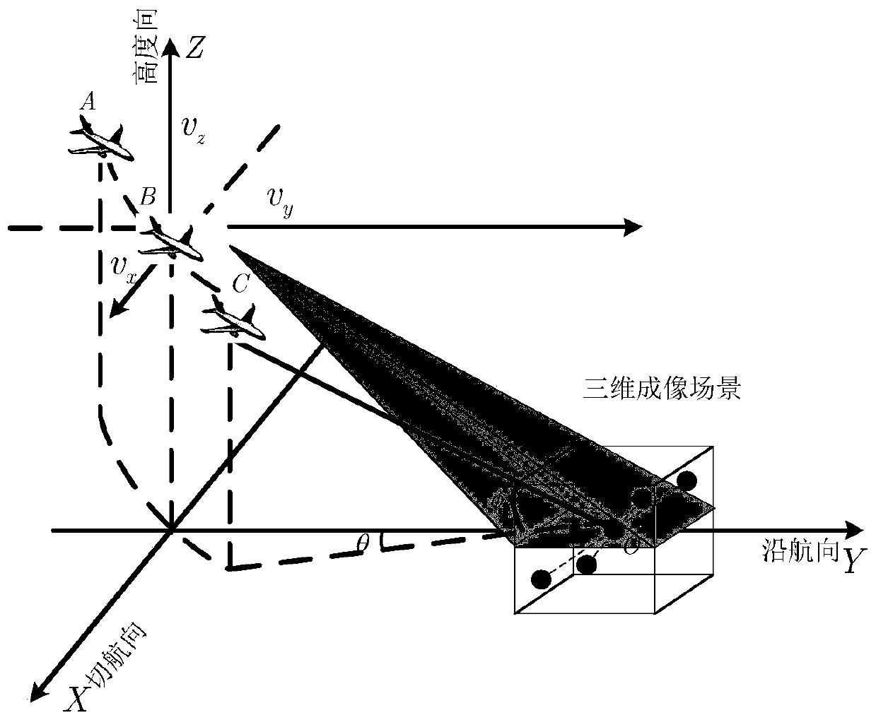
[0033] 1.1 Based on the geometric vector method to represent the instantaneous slant distance history between SAR configuration projectiles and targets: see figure 2 , figure 2 is the spatial geometric configuration diagram of the missile-borne millimeter-wave forward-looking tangential SAR, which is the SAR configuration mentioned in the present invention, figure 2 Among them, the speed of the radar platform in the x-axis, y-axis and z-axis is V X (n), V Y (n) and V Z (n) indicates that the observation area is the shaded part in the figure, and the black dots represent target scattering points. The target moves on a tangential curved track in three-dimensional space, and its beam always illuminates the obse...

Embodiment 3

[0062] The radar forward-looking three-dimensional imaging method based on the descending segment curve track is the same as embodiment 1-2, and the vectorized decomposition of the echo signal described in step (2) includes the following steps:

[0063] 2.1 Divide the observation scene: Assuming that the launch signal is a linear frequency modulation signal, according to the curved trajectory of the missile's descending section, the three-dimensional space scene of the radar forward-looking tangential target imaging is evenly divided, and the observation scene is divided into three-dimensional uniform space in combination with the spatial sparse distribution characteristics of the target scattering points. distributed grid If the target is accurately calibrated on the preset grid point, the echo signal of the input SAR configuration is expressed as:

[0064]

[0065] where i and j represent fast time and slow time sampling points respectively, δ mnl is the target amplitud...


PUM


Abstract

The invention discloses a radar foresight three-dimensional imaging method based on a descending segment curve trajectory. The problem that a descending segment curve trajectory radar can only form atwo-dimensional image for a target is solved. The method comprises the steps that an echo signal mathematical model is established; a mathematical model of SAR configuration is vectorized to acquire athree-dimensional wavenumber spectrum of SAR configuration; the coordinate information of the target and a target scattering coefficient are acquired; and radar foresight three-dimensional imagingof the descending segment curve trajectory is realized. According to the invention, the influence of a one-dimensional weakly coupled wavenumber spectrum is ignored in the three-dimensional wavenumber spectrum; the two-dimensional coordinate information of the scene target corresponding to another two-dimensional wavenumber spectrum is extracted; an optimal processing algorithm based on l1 optimization is used to acquire the target scattering coefficient; the unique tangential flight characteristics of a missile are used to add spatial freedom to achieve a synthetic aperture in the tangentialdirection; three-dimensional imaging is carried out on the target to solve the problem that a traditional missile-borne SAR model has a certain angle with the target spacing to achieve azimuth high-resolution; and the method is suitable for a missile-borne high-resolution radar guidance technology.

Description

technical field [0001] The invention belongs to the technical field of new system radar imaging, and establishes a new system model based on the snake-shaped tangential motion characteristics of missiles, specifically a radar forward-looking three-dimensional imaging method based on the curve trajectory of the descending section, which is used in missile-borne high-resolution radar guidance technology middle. Background technique [0002] At present, the missile-borne Synthetic Aperture Radar (SAR) seeker adopts the spotlight SAR imaging mode in the missile descent section, and obtains the SAR imaging of the target scene in real time through high-resolution two-dimensional focused imaging of the target scene, and Matching and positioning with the set SAR reference image to realize the positioning and identification of the target. However, conventional synthetic aperture radar imaging technology obtains high-resolution microwave images of distance and azimuth by transmitting...

Claims


Application Information

Patent Timeline
Patent Type & Authority Applications(China)
IPC IPC(8): G01S13/90G01S7/41
CPCG01S13/90G01S7/415G01S13/9011G01S13/9043
Inventor 李亚超顾彤全英汇王晓菲武春风崔奇
Owner XIDIAN UNIV
Why Eureka
Try Eureka