Plasma processing device capable of reducing pollution particles and method thereof

A processing device and plasma technology, applied in the direction of discharge tube, metal material coating process, coating, etc., can solve the problems of wafer hidden dangers, wafer pollution, etc., and achieve the goal of improving pollution, significant effect and high efficiency Effect

Active Publication Date: 2019-07-02
ADVANCED MICRO FAB EQUIP INC CHINA
View PDF5 Cites 3 Cited by
  • Summary
  • Abstract
  • Description
  • Claims
  • Application Information

AI Technical Summary

Problems solved by technology

This process is effective for the protection of the current wafer, but there is still a hidden danger for the next wafer, because as the gas in the transfer chamber 2 rushes to the particles of the shielding plate 16 in the PM, it will be blocked by the shielding plate 16 And drop a part of the area formed between the bushing 12, the shielding plate 16 and the cavity 13, this area is a dead zone, that is, it is not easy to be sucked away by the vortex pump 15 immediately.
[0006] But when it is the turn of the second wafer transfer, the gas in the cavity of the transfer chamber 2 flows to the plasma processing device 1 again, and the gas in the transfer chamber 2 flows to the cavity of the plasma processing device 1 again. Disturbance will disturb the particles dropped during the last transfer process in the dead zone, and bring the disturbed particles to the electrostatic chuck and wafer, thus contaminating the wafer
Among them, the dead zone formed between the liner 12, the shielding plate 16 and the cavity 13, because there is no effective gas flow path, the particles falling in the dead zone will eventually contaminate the subsequent wafer transfer.

Method used


Image

  • Plasma processing device capable of reducing pollution particles and method thereof
  • Plasma processing device capable of reducing pollution particles and method thereof
  • Plasma processing device capable of reducing pollution particles and method thereof

Examples


Embodiment 1

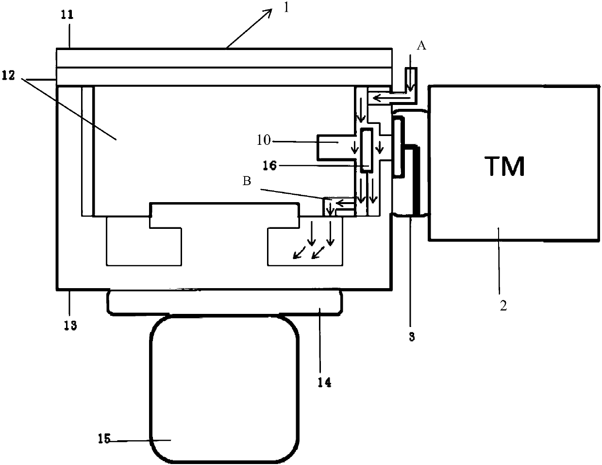
[0040] Such as figure 2 As shown, in the first embodiment, the lower part of the bushing 12 is provided with a hole B, and the flow space formed by the outer wall of the bushing and the inner wall of the cavity under the baffle plate 16 communicates with the inner space of the bushing 12 through the hole B, Create an efficient gas flow path.

[0041] After finishing the first wafer transfer and before the second wafer transfer, the cavity 13 is provided with a gas pipeline connected to the cleaning gas source supplying the cleaning gas A, the cleaning gas A (such as argon Ar etc.) After entering the cavity 13, the air curtain will be formed by flowing vertically downward along the baffle plate 16, that is, it will flow from top to bottom along the gap between the inner wall of the cavity and the outer wall of the bushing, and will pass through the outer wall of the bushing and the outer wall of the bushing under the baffle plate 16. The flow space formed around the cavity pa...

Embodiment 2

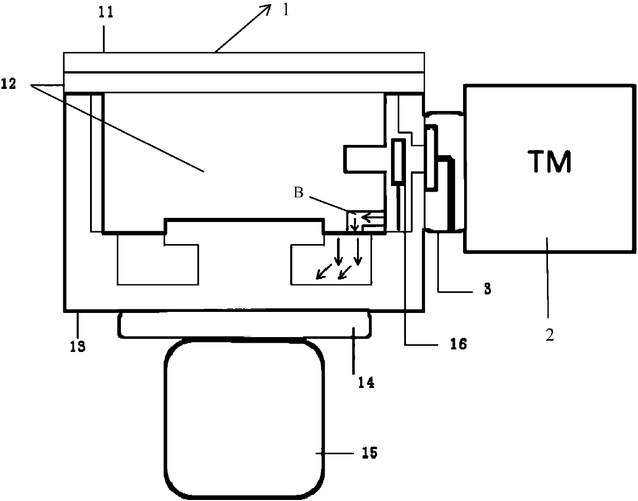
[0044] Such as image 3 As shown, in the second embodiment, the lower part of the bushing 12 is provided with a hole B, and the flow space formed around the outer wall of the bushing and the inner wall of the cavity under the baffle plate 16 communicates with the inner space of the bushing 12 through the hole B, Create an efficient gas flow path.

[0045] In the second embodiment, no gas pipeline is provided on the cavity 13 to communicate with the clean gas source for supplying the clean gas, that is, the upper end of the cavity 13 is not filled with clean gas, and only the gas flow path is communicated with the vortex pump 15 .

[0046] After finishing the first wafer transfer and before the second wafer transfer, when the vortex pump 15 is turned on, the last transfer process falls on the outer wall of the bushing and the cavity 13 formed around the shielding plate 16. After the pollution particles in the space are pulled by the vortex pump 15, the space formed by the oute...


PUM


Abstract

The invention discloses a plasma processing device capable of reducing pollution particles and a method thereof. The plasma processing device comprises a cavity and a lining. A dielectric window is arranged above the lining. The cavity, the lining and the dielectric window are enclosed to form a reaction cavity. The inner bottom of the reaction cavity comprises a base for placing a wafer. A vacuumpumping device for pumping gas in the reaction cavity to maintain low pressure in the reaction cavity is arranged on the lower part of the base. A baffle plate shielding between the opening on the side wall of the cavity and the opening on the side wall of the lining is arranged in the cavity to block the pollution particles in the gas flowing from the transmission cavity to the reaction cavity.A hole groove is arranged on the lower part of the lining. The flow space formed by enclosing of the outer wall of the lining and the inner wall of the cavity under the baffle plate is communicated with the inner space of the lining through the hole groove so that the pollution particles are evacuated by the vacuum pumping device. The current wafer is ensured not to be contaminated, the contamination of the next transmission wafer can be improved and the cleaning gas can be piped in so that the effect of taking out the contaminated particles of the reaction cavity can be more remarkable and the efficiency is higher.

Description

technical field [0001] The invention relates to the technical field of anti-corrosion protection of etching equipment, in particular to a plasma treatment device and a method thereof which can reduce pollution particles. Background technique [0002] In the prior art, during the transfer process between the transmission chamber (Transmission Machine, TM for short) and the plasma processing device 1 (Plasma Machine, PM for short), due to the imbalance of the air pressure in the two chambers, there will be a gap between the two chambers. As the gas flows, the particles suspended in each cavity will flow to another cavity with the gas, causing particle pollution in the cavity. [0003] Such as figure 1 Shown is a simplified schematic diagram of an etching (ETCH) system, which is composed of a transfer chamber 2 , a vacuum valve 3 (slit valve) and a plasma processing device 1 . Wherein, the plasma processing apparatus 1 includes a dielectric window 11 (insulation window), a li...

Claims


Application Information

Patent Timeline
Patent Type & Authority Applications(China)
IPC IPC(8): H01J37/32
CPCH01J37/32009H01J37/32394H01J37/32449H01J37/32513H01J37/32477H01J37/321C23C16/4409C23C16/4408C23C16/4412C23C16/4404H01J2237/022C23C16/52
Inventor 倪图强左涛涛刘身健陈星建万磊
Owner ADVANCED MICRO FAB EQUIP INC CHINA
Why Eureka
Try Eureka