
Cathode electron enhancement device

A technology for boosting device and cathode electron emission, which is applied in the direction of electron multiplier dynode, electron multiplier details, dynode, etc. It can solve the problems of reduced service life of thermionic emission source, large heating wire current, etc., and achieve the realization of cathode Electron emission current, to achieve the effect of focusing

Pending Publication Date: 2019-07-02
SOUTHWESTERN INST OF PHYSICS +1
View PDF0 Cites 1 Cited by
  • Summary
  • Abstract
  • Description
  • Claims
  • Application Information

AI Technical Summary

Problems solved by technology

For a thermionic emission source, in order to obtain a larger electron emission current, a larger heating filament current will be required, which means that the life of the thermionic emission source will be further reduced

Method used


Image

  • Cathode electron enhancement device
  • Cathode electron enhancement device
  • Cathode electron enhancement device

Examples


Embodiment Construction

[0015] The present invention will be further described below in conjunction with the accompanying drawings and specific examples.

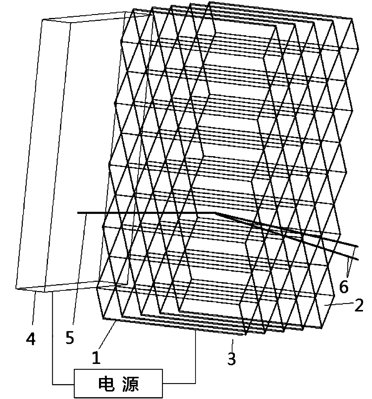
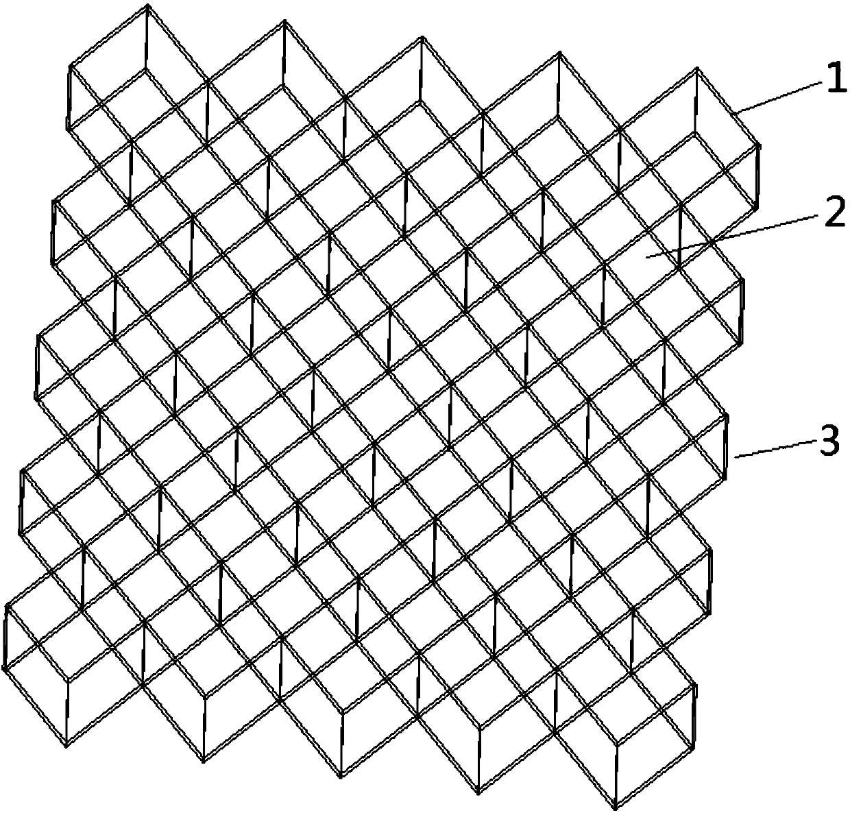
[0016] Such as figure 1 As shown, a cathode electron enhancement device of the present invention is composed of a high-voltage power supply, a cathode electron emission source (4) and a zigzag elongated metal sheet (1) with a certain width and length and a certain angle in section The sheet metal group (3) constitutes.

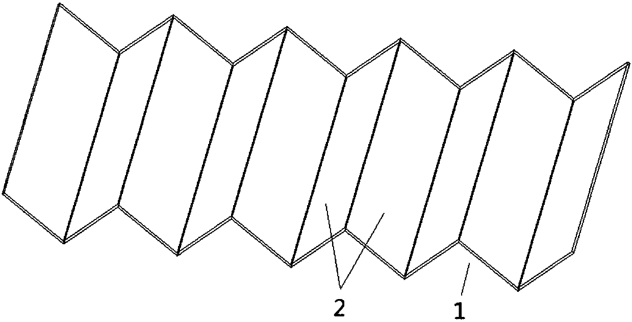
[0017] Such as figure 2 As shown, the metal thin plate (1) is an elongated thin plate with a certain thickness and a certain width, and a zigzag cross-section. The material is sputtered metal such as molybdenum or tungsten.

[0018] In order to increase the secondary electron emission coefficient of the surface (2) of the thin metal plate (1), the plasma injection or coating method is applied to the thin metal plate (1), and it is injected or coated within a certain depth on the surface (2) of the thin metal plate (1). Chemic...


PUM


Abstract

The invention belongs to an enhancement device, and particularly relates to a cathode electron enhancement device. The cathode electron enhancement device is composed of a power supply, a cathode electron emission source and a metal sheet group, wherein the metal sheet group is arranged at the electron emission end of the cathode electron emission source, the metal sheet group is composed of a plurality of long strip-shaped metal sheets, and the cross section of the metal sheet group is in a zigzag shape. The cathode electron enhancement device has the remarkable effects that the electrons emitted from the cathode are accelerated by the metal sheet group with injection of cesium, magnesium and the like under the action of a certain voltage to impact the surface of the metal sheet group togenerate secondary electron emission so as to realize electron multiplication and realize enhancement of the cathode electron emission current. Meanwhile, the shape of the metal sheet group can be adjusted, the emission electrons of the cathode electron emission source can be regulated and the electron optical effect such as focusing can be realized.

Description

technical field [0001] The invention belongs to a booster, in particular to a cathode electron booster. Background technique [0002] Cathode electron emission is widely used in display technology, lighting technology, X-ray tube, negative ion generation and other fields. When cathode electrons of a certain energy bombard the surface of a metal material, if the energy of the electrons is large enough, the electrons on the surface of the material will be knocked down, resulting in electron multiplication and enhancement of cathode electrons, which is secondary electron emission. In order to improve the secondary electron emission coefficient of the material, a layer of low field electron emission layer can be prepared on the surface of the material by means of injection or coating. [0003] Cathode electron sources can be divided into: thermionic emission sources and field electron emission sources. Thermionic emission is currently the most widely used and most mature techn...

Claims


Application Information

Patent Timeline
IPC IPC(8): H01J43/10
CPCH01J43/10
Inventor 李建童洪辉王坤但敏金凡亚
Owner SOUTHWESTERN INST OF PHYSICS
Learn More