Method and fluid pump for conveying fluid in a fluid circuit of a motor vehicle

A fluid circuit, fluid pump technology, applied in the direction of fluid parameters, machines/engines, pumps, etc., can solve problems such as lack of regulation, affecting the efficiency of fluid pumps or motor vehicle transmissions, and inability to ensure efficient fluid delivery, achieving favorable determination, less cost effect

Active Publication Date: 2020-11-03
BROSE FAHRZEUGTEILE GMBH & CO KG
View PDF6 Cites 0 Cited by
  • Summary
  • Abstract
  • Description
  • Claims
  • Application Information

AI Technical Summary

Problems solved by technology

However, due to the lack of regulation, efficient delivery of the fluid cannot be ensured, thereby adversely affecting the efficiency of the fluid pump or motor vehicle transmission

Method used


Image

  • Method and fluid pump for conveying fluid in a fluid circuit of a motor vehicle
  • Method and fluid pump for conveying fluid in a fluid circuit of a motor vehicle
  • Method and fluid pump for conveying fluid in a fluid circuit of a motor vehicle

Examples


Embodiment Construction

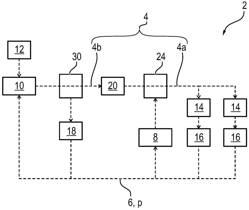
[0042] figure 1 The hydraulic system 2 shown in is suitable and set up for operating and lubricating a motor vehicle transmission, in particular a shift transmission, of a motor vehicle (not shown). To this end, the hydraulic system 2 comprises a fluid or oil circuit 4 shown in dashed lines for conducting (hydraulic) fluid 6 , in particular (transmission) oil. The hydraulic system 2 has two fluid or oil pumps 8 and 10 for conveying the oil 6 in the oil circuit 4 . The oil pump 8 is designed here as a main pump, while the oil pump 10 is designed as an auxiliary or supplementary pump of the oil circuit 4 .

[0043] In this case, the oil pump 8 is coupled to the internal combustion engine of the motor vehicle and can be functionally driven by the internal combustion engine for conveying the oil 6 . The oil pump 10 is implemented electrically and has a driven electric motor 12 . The electric motor 12 is designed, for example, as a brushless DC motor and has a rotatably mounted ...


PUM


Abstract

The invention relates to a method for conveying a fluid (6) of a fluid circuit (4) with an electric fluid pump (10) of a motor vehicle, in particular an oil pump, wherein the fluid circuit (4) is pumped by means of the fluid pump (10) The fluid pressure (p) of the fluid (6) in is adjusted to the target pressure (p 目标 ), and wherein the actual pressure of the fluid (6) (p 实际 ).

Description

technical field [0001] The invention relates to the field of pumps, preferably electrically or electrically operated or driven (fluid) pumps, and to a circuit for conveying a fluid with an electric fluid pump in a motor vehicle, in particular in a motor vehicle transmission fluid approach. The invention also relates to a fluid pump operating according to this method and to a motor vehicle transmission having such a fluid pump. In this context, a fluid pump is to be understood in particular as an auxiliary or main pump, in particular an oil pump, in or for a motor vehicle. Background technique [0002] Electric fluid pumps and in particular also so-called auxiliary pumps or auxiliary pumps are used, for example, to deliver oil as (hydraulic) fluid for control tasks or to cool vehicles driven, for example, by an internal combustion engine, with hybrid technology or electric drive A particularly moving part or component of (a motor vehicle). Such an oil pump usually generate...

Claims


Application Information

Patent Timeline
Patent Type & Authority Patents(China)
IPC IPC(8): F04B49/06
CPCF04B17/03F04B49/06F04B49/065F16H59/68F16H61/0031F04B2201/1202F04B2203/0207F04B2203/0209F04B2205/05F04B2205/14F16H2059/683F16H61/00F04B49/08F16H61/0265F16H61/30F16H2061/0078
Inventor 阿达尔沙·干乍纳克里斯蒂安·比尼克
Owner BROSE FAHRZEUGTEILE GMBH & CO KG
Why Eureka
Try Eureka