Portable multifunctional breathing mask

A multi-functional, breathing mask technology, applied in the direction of respiratory protection devices, fire rescue, life-saving equipment, etc., can solve the problem of not being able to pre-heat the cold air, achieve the effect of increasing the temperature, improving the comfort of use, and enhancing the degree of fit

Active Publication Date: 2019-07-05
晏雨扬
View PDF5 Cites 0 Cited by
  • Summary
  • Abstract
  • Description
  • Claims
  • Application Information

AI Technical Summary

Problems solved by technology

[0003] The present invention intends to provide a portable multifunctional breathing mask to solve the problem that the existing masks cannot preheat the inhaled cold air

Method used


Image

  • Portable multifunctional breathing mask
  • Portable multifunctional breathing mask
  • Portable multifunctional breathing mask

Examples


Embodiment 1

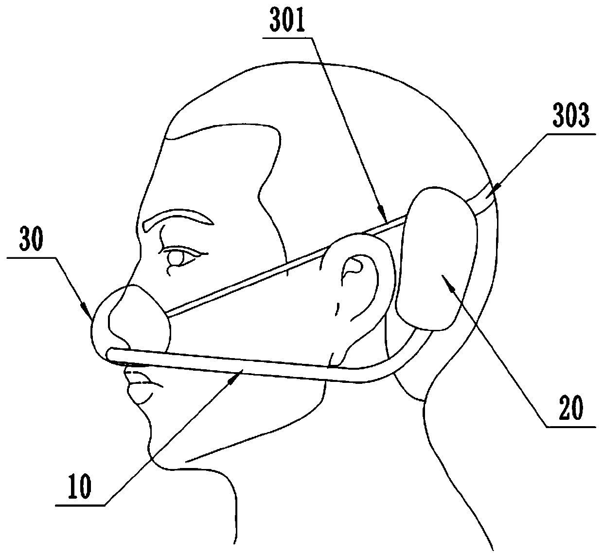
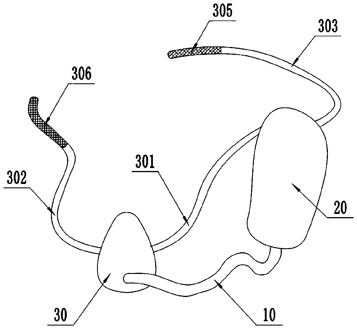
[0045] This embodiment is basically as figure 1 , figure 2 Shown: a portable multifunctional breathing mask, including a dual-flow airway 10, a heat exchange chamber 20, and a cover body 30 that can form a sealed space with the user's nasal cavity. The contact between the cover body 30 and the user's face is fixedly connected with flexible sealing silicone , to ensure that a sealed space is formed between the mask body 30 and the user's nose.

[0046] The two sides of the cover body 30 are respectively fixedly connected with an elastic fixing belt I 301 and an elastic fixing belt II 302 , and the right end of the elastic fixing belt I 301 is fixedly connected with the heat exchange chamber 20 . The side wall of the heat exchange chamber 20 is fixedly connected with an elastic fixing belt III303, the elastic fixing belt II302 is fixedly connected with a connecting piece II306, and the elastic fixing belt III303 is fixedly connected with a connecting piece I305, and the connec...

Embodiment 2

[0055] The difference between this embodiment and Embodiment 1 is that: Figure 5 , Figure 6 and Figure 7 As shown, the side wall of the heat exchange chamber 20 is fixedly connected with a functional chamber 40, and the functional chamber 40 is connected with the right chamber 230. Specifically, a through groove 231 is opened on the side wall of the right chamber 230, and the through groove 231 communicates with the right chamber. chamber 230 and functional chamber 40 . The exhalation pipe 110 passes through the functional chamber 40 and communicates with the left chamber 220 , and the inhalation pipe 120 communicates with the functional chamber 40 .

[0056] The exhalation pipe 110 is communicated with a branch pipe 111, and the branch pipe 111 is located in the function room 40, and the branch pipe 111 is blocked with a wetted cotton ball 112, non-toxic and corrosion-resistant soft polypropylene microfiber or polyurethane foam filler. In an embodiment, cotton balls 112...

Embodiment 3

[0062] The difference between this embodiment and Embodiment 2 is that: Figure 8 As shown, the functional chamber 40 is filled with liquid, and the liquid level of the liquid overflows the left end of the coarse-pored sponge block 113, so that the coarse-pored sponge block 113 can absorb the liquid inside. The liquid is deionized water or sterile water or sterile water / deionized water added with lung-clearing liquid, and the bottom end of the branch pipe 111 is below the liquid level. In this embodiment, the liquid is sterile water added with lung-clearing medicinal liquid.

[0063] The side wall of the functional room 40 is provided with a cavity 431, in which a number of heating wires 432 are installed. The output terminal of the power supply is electrically connected to the power supply I434, and each heating wire 432 forms an independent electrical circuit with the switch I433 and the power supply I434. The specific circuit connection is as follows: Figure 9 shown.

...


PUM


Abstract

The invention relates to the technical field of protective articles and particularly discloses a portable multifunctional breathing mask. The portable multifunctional breathing mask comprises a double-flow air guiding tube, a heat exchanging chamber and a mask body capable of forming a sealed space with the nasal cavity of a user, wherein one end of the double-flow air guiding tube is communicatedwith the mask body; the double-flow air guiding tube comprises an inhalation tube and an exhalation tube; the exhalation tube is connected inside the inhalation tube in a sleeving manner; a pluralityof thermal conductive rods are inserted in the tube wall of the exhalation tube; one ends of the thermal conductive rods are arranged in the exhalation tube; the other ends of the thermal conductiverods are arranged outside the exhalation tube; a heat exchanging sheet is arranged in the heat exchanging chamber to separate the heat exchanging chamber into a left chamber and a right chamber; the left chamber is communicated with a pipeline I; the right chamber is communicated with a pipeline II; an exhalation check valve and an inhalation check valve are respectively arranged on the pipeline Iand the pipeline II; the exhalation tube is communicated with the left chamber; and the inhalation tube is communicated with the right chamber. The mask disclosed by the invention has the beneficialeffects that the inhaled cold air can be preheated to reduce the stimulation of the cold air on the breathing system of the user.

Description

technical field [0001] The invention relates to the technical field of protective equipment, and specifically discloses a portable multifunctional breathing mask. Background technique [0002] In recent years, coal burning, motor vehicle exhaust, industrial emissions, dust and other reasons have caused the air quality in most parts of our country to decline year by year. This causes disease. The masks currently on the market mainly focus on filterability, ventilation, and airtightness. The material is mainly cotton yarn, so most masks are suitable for the southern regions with humid climate and high temperature. In northern regions with a dry and cold climate, in addition to air pollutants, dry cold air is the main cause of stimulating the respiratory system. For patients with chronic respiratory diseases (chronic bronchitis, emphysema, asthma, allergic rhinitis), cold air will stimulate the glands to increase mucus secretion, weaken ciliary movement, constrict mucosal blo...

Claims


Application Information

Patent Timeline
IPC IPC(8): A62B7/10A62B9/06
CPCA62B7/10A62B9/06
Inventor 晏雨扬
Owner 晏雨扬
Why Eureka
Try Eureka