Thin-wall piece milling vibration restraining method based on movable support

A milling flutter and dynamic support technology, which is applied in the direction of manufacturing tools, maintenance and safety accessories, metal processing machinery parts, etc., can solve the problems of long time consumption, fast prediction of limited stable domain, large amount of experiments, etc.

Active Publication Date: 2019-07-05
NORTHWESTERN POLYTECHNICAL UNIV
View PDF5 Cites 6 Cited by
  • Summary
  • Abstract
  • Description
  • Claims
  • Application Information

AI Technical Summary

Problems solved by technology

[0004] The above documents have all carried out chatter suppression in the milling process; however, in the actual operation process, the method disclosed in Document 1 requires a large amount of experiments and requires repeated modal percussion experiments, which consumes a lot of time and is relatively low in efficiency
The method disclosed in Document 2 is mainly aimed at the poor rigidity of the spindle during the machining process. For the thin-walled parts with poor rigidity, the chatter suppression effect is not obvious, and the versatility is relatively poor.
This limits the suppression of milling chatter and the rapid prediction of the stable domain during milling of thin-walled parts

Method used


Image

  • Thin-wall piece milling vibration restraining method based on movable support
  • Thin-wall piece milling vibration restraining method based on movable support
  • Thin-wall piece milling vibration restraining method based on movable support

Examples


Embodiment 1

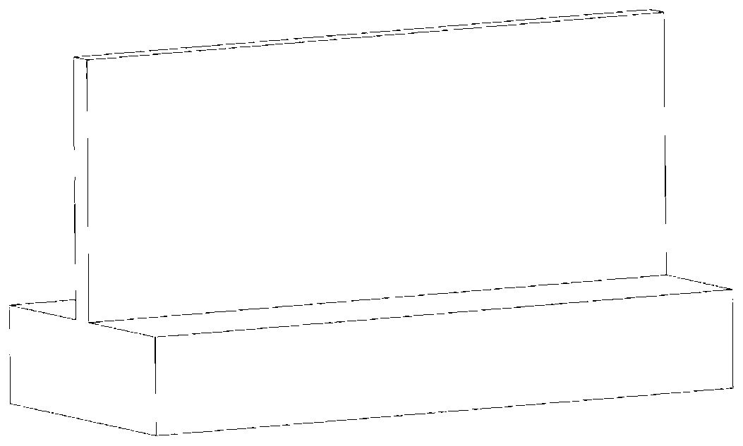
[0137] Embodiment 1: the plane straight thin plate size is 100mm × 40mm × 4mm, the material is aluminum alloy 7075, the modulus of elasticity is 71.7GPa, and the density is 2830kg / m 3 , Poisson's ratio is 0.33.

[0138] 1. According to the milling characteristics of thin-walled parts, a multi-point contact milling dynamic model considering the deformation of the tool and the workpiece is established; the contact area between the tool and the workpiece is divided into 24 microelements along the axial direction, and the milling Concentrate forces on nodes and find dynamic milling forces:

[0139]

[0140] The dynamic state equation of the milling system is:

[0141]

[0142] m W,0 ,C W,0 , K W,0 Represents the mass, damping, and stiffness matrices of the initial workpiece; and Q W (t) represents the acceleration, velocity and displacement vector of the workpiece under physical coordinates;

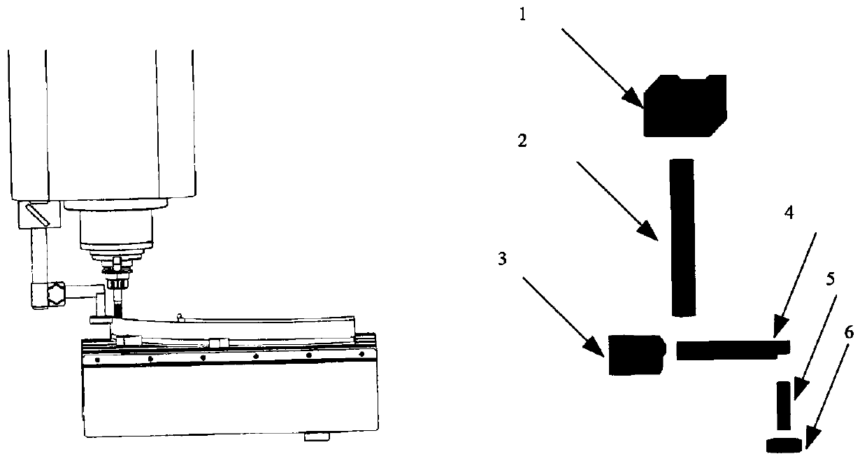
[0143] two, figure 1 Middle part 1 is a magnetic suction seat, part 2, pa...

Embodiment 2

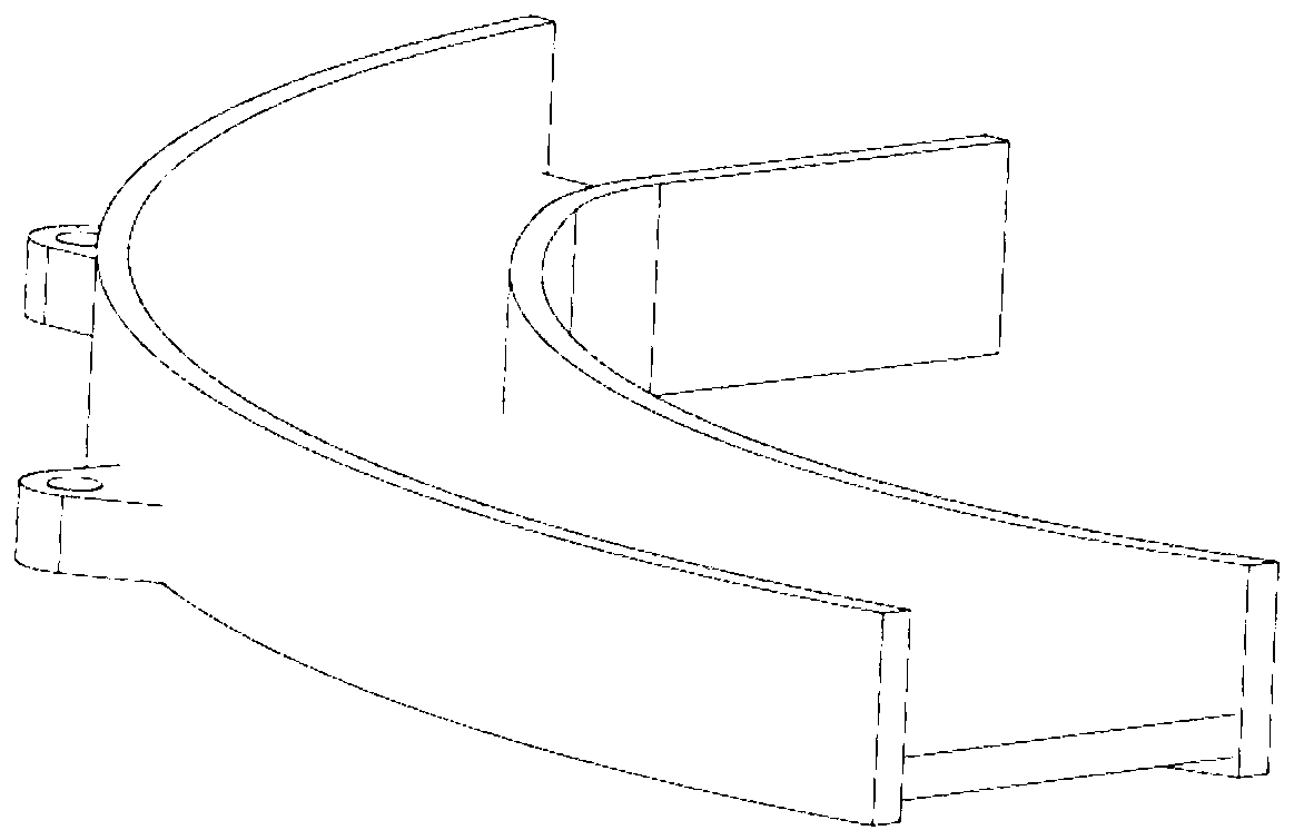
[0198] Example 2: The size of the curved thin plate is 319mm long, 39mm high, 3.6mm thick, and the radius of curvature is 178mm; the material is aluminum alloy 7075, the modulus of elasticity is 71.7GPa, and the density is 2830kg / m 3 , Poisson's ratio is 0.33.

[0199] 1. Aiming at the milling characteristics of thin-walled parts, establish a multi-point contact milling dynamics model that simultaneously considers the deformation of the tool and the workpiece; divide the contact area between the tool and the workpiece into 28 microelements along the axial direction, and divide the milling Concentrate forces on nodes and find dynamic milling forces:

[0200]

[0201] The dynamic state equation of the milling system is:

[0202]

[0203] m W,0 ,C W,0 ,K W,0 Represents the mass, damping, and stiffness matrices of the initial workpiece; and Q W (t) represents the acceleration, velocity and displacement vector of the workpiece under physical coordinates;

[0204] two, ...


PUM


Abstract

The invention relates to a thin-wall piece milling vibration restraining method based on a movable support. The mass, rigidity and a damping matrix of a workpiece are obtained through the finite element; equivalent stiffness and damping provided through the movable support are calculated through the contact theory and assembled to rigidity and a damping matrix of an initial workpiece; and finally,dynamics parameters of the workpiece at different tool position points are rapidly obtained through a numerical calculation method, and stability prediction is conducted. The functions of efficient restraining of vibration and rapid prediction of vibration stability in the whole machining process are achieved, and the material removal rate in the milling process is improved by 67% to the maximumin the embodiment.

Description

technical field [0001] The invention relates to a chatter prediction and suppression method in the milling process of thin-walled parts, which is mainly applicable to the rapid prediction and chatter suppression of the stable region in the milling process of thin-walled parts. Background technique [0002] Document 1 "K. Kolluru, D. Axinte, Novel ancillary device for minimizing machining vibrations in thin wall assemblies, International Journal of Machine Tools and Manufacture 2014, 85:79–86." A suppression device is used to suppress the occurrence of chatter during milling of thin-walled parts. This method uses the experimental knocking method to obtain the dynamic parameters of the workpiece after using the vibration suppression device, and then predicts the chatter stability. [0003] Document 2 "Y.Lei, S.H.Sun, Z.X.Pan, D.H.Ding, O.Gienke, W.H.Li, Mode couplingchatter suppression for robotic machining using semi-active magnetic orheological elastomers absorber, Mechanic...

Claims


Application Information

Patent Timeline
Patent Type & Authority Applications(China)
IPC IPC(8): B23Q11/00G06F17/50
CPCB23Q11/0039G06F30/17G06F30/23G06F2119/06
Inventor 张卫红党学斌万敏杨昀
Owner NORTHWESTERN POLYTECHNICAL UNIV
Why Eureka
Try Eureka