
Centrifugal dewatering and drying integrated machine

A centrifugal dewatering and integrated machine technology, which is applied in the fields of dewatering/drying/concentrating sludge treatment, chemical instruments and methods, water/sludge/sewage treatment, etc. Advanced problems, to achieve the effect of good effect and high dehydration rate

Pending Publication Date: 2019-07-05
厦门鹭昆机电设备有限公司
View PDF0 Cites 3 Cited by
  • Summary
  • Abstract
  • Description
  • Claims
  • Application Information

AI Technical Summary

Problems solved by technology

[0002] At present, the problem of excess sludge treatment in urban sewage plants is very serious, and there is a great demand for water pollution prevention and treatment and sludge reduction. At present, the development level in the field of excess sludge reduction and excess sludge reuse is relatively low. Compared with developed countries, there is still a big gap
[0003] The remaining sludge is mainly incinerated and sanitary landfill at this stage, accounting for about 80% of the treatment capacity. There is no effective sludge drying and reduction equipment from the source, resulting in high cost and low efficiency in the sludge treatment process. It cannot meet the current environmental protection development requirements, so it is necessary to provide a centrifugal dehydration and drying all-in-one machine with better dehydration and drying effect

Method used


Image

  • Centrifugal dewatering and drying integrated machine
  • Centrifugal dewatering and drying integrated machine
  • Centrifugal dewatering and drying integrated machine

Examples


Embodiment Construction

[0020] The following will clearly and completely describe the technical solutions in the embodiments of the present invention with reference to the accompanying drawings in the embodiments of the present invention. Obviously, the described embodiments are only some, not all, embodiments of the present invention. Based on the embodiments of the present invention, all other embodiments obtained by persons of ordinary skill in the art without making creative efforts belong to the protection scope of the present invention.

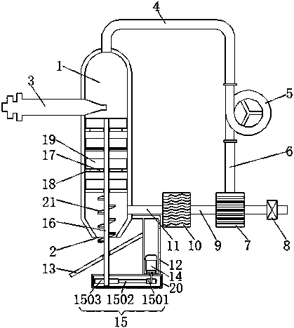
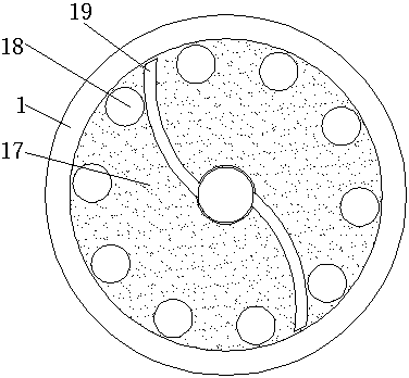
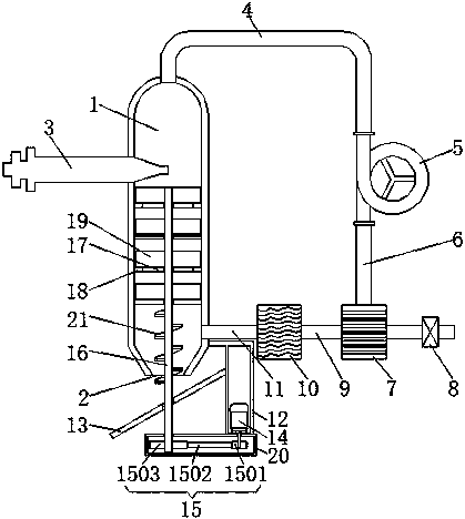
[0021] Such as Figure 1-2 As shown, the present invention provides a technical solution: a centrifugal dehydration and drying integrated machine, comprising a tank body 1, the bottom of the tank body 1 is provided with a discharge port 2, and the side surface of the tank body 1 is provided with a centrifugal dehydrator 3, The centrifugal dehydrator 3 is located on the left side of the tank body 1 and communicates with the tank body 1. The top of the tank body...


PUM


Abstract

The invention discloses a centrifugal dewatering and drying integrated machine, and relates to the technical field of dehydration and drying devices. The centrifugal dewatering and drying integrated machine comprises a tank body, a discharging outlet is formed in the bottom of the tank body, a centrifugal dewatering machine is arranged on the lateral surface of the tank body, the top of the tank body is provided with a steam collecting pipe, and a steam outlet end of the steam collecting pipe is fixedly connected with an air inlet end of a negative pressure blower. An air outlet end of the negative pressure blower is fixedly connected with an air inlet end of a round pipe, an air outlet end of the round pipe is fixedly connected with an air inlet end of a waste heat recovery device, the other air inlet end of the waste heat recovery device is provided with a control valve, and an air outlet end of the waste heat recovery device is fixedly connected with an air inlet end of a heating device through a first connecting pipe. By arranging the negative air blower, the waste heat recovery device, a motor, a disc and a sludge scraping plate, the problem that an existing sludge treatment device is poor in sludge dewatering and drying effect is solved.

Description

technical field [0001] The invention relates to the technical field of dehydration and drying devices, in particular to an integrated centrifugal dehydration and drying machine. Background technique [0002] At present, the problem of excess sludge treatment in urban sewage plants is very serious, and there is a great demand for water pollution prevention and treatment and sludge reduction. At present, the development level in the field of excess sludge reduction and excess sludge reuse is relatively low. Compared with developed countries, there is still a big gap. [0003] At this stage, the remaining sludge is mainly incinerated and sanitary landfill, accounting for about 80% of the treatment capacity. There is no more effective sludge drying and reduction equipment from the source, resulting in high cost and low efficiency in the sludge treatment process. It cannot meet the current environmental protection development requirements, so it is necessary to provide a centrif...

Claims


Application Information

Patent Timeline
Patent Type & Authority Applications(China)
IPC IPC(8): C02F11/127C02F11/13
CPCC02F11/127C02F11/12
Inventor 胡永祥
Owner 厦门鹭昆机电设备有限公司
Learn More