
Multifunctional heat treatment device for crankshaft machining device

A heat treatment device and crankshaft processing technology, applied in heat treatment furnaces, heat treatment equipment, quenching devices, etc., can solve the problems of not having the ability to remove residues on the surface of the crankshaft to prevent pollution, unable to hoist different types of crankshafts, and inconvenient for cooling and storage of crankshafts, to ensure that the The effect of heat treatment, the addition of anti-pollution function, and the effect of meeting the needs of automatic processing

Active Publication Date: 2019-07-05
滨州鲁德曲轴有限责任公司
View PDF5 Cites 2 Cited by
  • Summary
  • Abstract
  • Description
  • Claims
  • Application Information

AI Technical Summary

Problems solved by technology

[0005] In order to solve the above-mentioned technical problems, the present invention provides a multifunctional heat treatment device for crankshaft processing, to solve the problem that the existing heat treatment device for crankshaft processing is not convenient for cooling and storing crankshafts after heat treatment, and crankshafts of different types cannot be hoisted , does not have the anti-pollution function of removing residues on the crankshaft surface and cannot handle the waste liquid after quenching, which easily affects the heat treatment process.

Method used


Image

  • Multifunctional heat treatment device for crankshaft machining device
  • Multifunctional heat treatment device for crankshaft machining device
  • Multifunctional heat treatment device for crankshaft machining device

Examples


Embodiment Construction

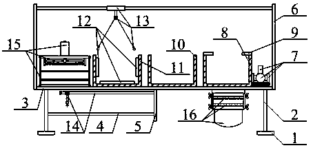
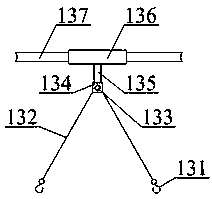
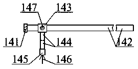
[0044] The present invention is described in detail below in conjunction with accompanying drawing, as appended figure 1 And attached figure 2 As shown, a multifunctional heat treatment device for crankshaft processing includes a support foot 1, a support leg 2, a base 3, a hollow plate 4, a support seat 5, a support column 6, a high-pressure water pump 7, a quenching chamber 8, and a fan 9 , an annealing chamber 10, a normalizing chamber 11, a heater 12, an automatic sliding adjustment crankshaft suspension hook structure 13, a slidable mobile crankshaft surface residue cleaner 14, an auxiliary cooling temporary storage rack 15 after crankshaft heat treatment and a waste liquid treatment collection tank after quenching Structure 16, the bolts at the middle positions of the supporting legs 1 are respectively mounted on the lower ends of the supporting legs 2; the longitudinal upper ends of the supporting legs 2 are bolted at the four corners of the bottom of the base 3 respec...


PUM


Abstract

The invention provides a multifunctional heat treatment device for a crankshaft machining device. The multifunctional heat treatment device comprises supporting footstands, supporting legs, a base, ahollowed-out plate, supporting seats, supporting columns, a high-pressure water pump, a quenching chamber, a fan, an annealing chamber, a normalizing chamber, a heater, an automatic sliding adjustingcrankshaft suspending hook structure, a slidable moving crankshaft surface residue clearer, a crankshaft after-heat-treatment auxiliary cooling temporary-storage frame and an after-quenching waste liquid treatment and collecting tank structure; the middles of the supporting footstands are transversely mounted at the lower ends of the supporting legs through bolts correspondingly; the upper ends ofthe supporting legs are longitudinally mounted at the four corners of the bottom of the base through bolts correspondingly. According to the multifunctional heat treatment device, through arrangementof crankshaft suspending hooks, pulling ropes and movable bolt nuts, the winding length of the pulling ropes is adjusted advantageously by releasing the movable bolt nuts, thus crankshafts can be suspended between the crankshaft suspending hooks, heat treatment work is conducted advantageously, and the demand of suspending the crankshafts of the different models is met.

Description

technical field [0001] The invention belongs to the technical field of heat treatment equipment, in particular to a multifunctional crankshaft processing device heat treatment device. Background technique [0002] Metal heat treatment is to heat a metal workpiece in a certain medium to a suitable temperature, and keep it at this temperature for a certain period of time, then cool it at a different speed, and control its performance by changing the surface or internal structure of the metal material. kind of craft. [0003] The Chinese patent publication number is CN108913866A, and the name of the invention is a kind of heat treatment device for crankshaft processing, including a normalizing chamber, an annealing chamber, and a quenching chamber. A support frame is arranged on one side of the normalizing chamber, and a An insulation door is arranged on the side, a moving frame is arranged above the support frame, a heater is arranged above the interior of the normalizing cha...

Claims


Application Information

Patent Timeline
IPC IPC(8): C21D9/30C21D1/63C21D1/28
CPCC21D1/28C21D1/63C21D9/0062C21D9/30Y02P10/20
Inventor 毛海堂张立平李翠翠
Owner 滨州鲁德曲轴有限责任公司
Learn More