Sensing device for flameout protection mechanism of gas stove
A sensing device and flameout protection technology, applied in the field of gas stoves, can solve the problems of difficult control, unstable performance, and many factors affecting the flame state, and achieve the effect of stable performance
- Summary
- Abstract
- Description
- Claims
- Application Information
AI Technical Summary
Problems solved by technology
Method used
Image
Examples
Embodiment 1
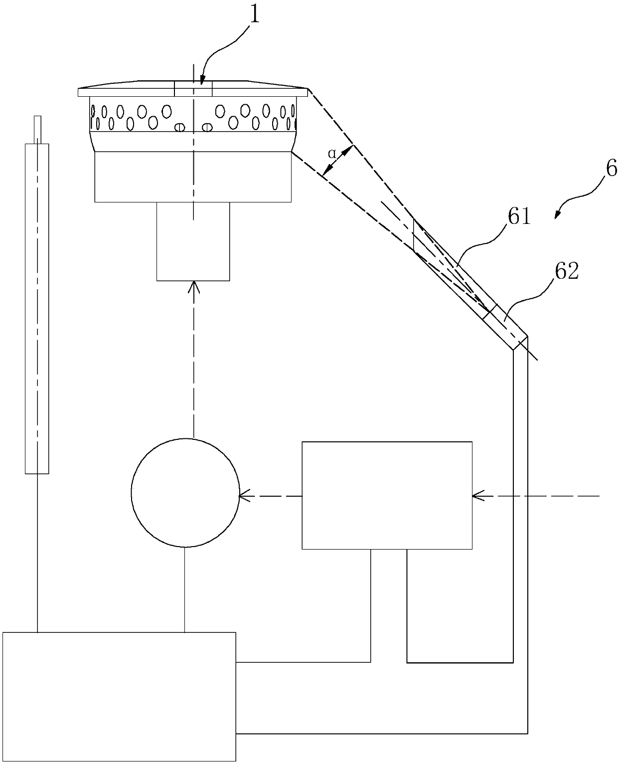
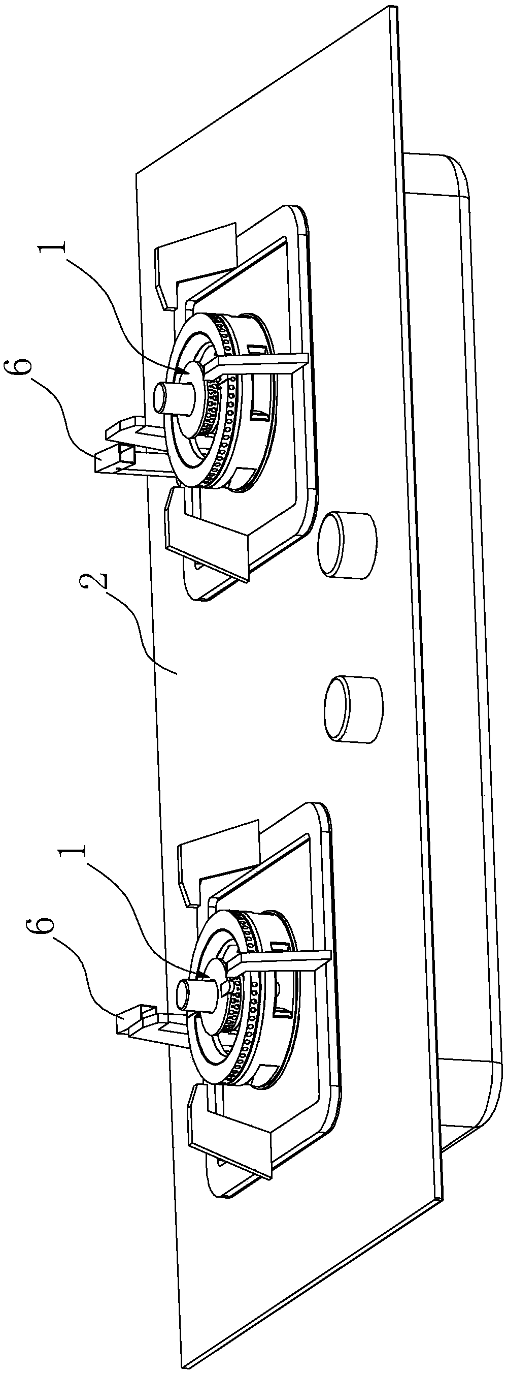
[0023] Such as figure 1 Shown is the first embodiment of the sensing device used in the flameout protection mechanism of the gas stove according to the present invention. The sensing device includes a burner 1 and a gas stove panel 2 .
[0024] in,
[0025] On the gas cooker panel 2 adjacent to the burner 1, a lighting mechanism 6 capable of detecting ultraviolet rays in the flame is arranged.
[0026] The lighting mechanism 6 includes a lighting tube 61 whose tube opening faces the burner 1 and an ultraviolet photosensitive tube 62 arranged in the lighting tube 61 .
[0027] The central line of the mouth of the lighting tube 61 is aligned with the burner 1 fire hole position. Make the maximum lighting angle of the lighting tube 61 not exceed the uppermost edge of the burner 1, avoid external ultraviolet interference, and ensure the reliability of the measurement.
[0028] In this embodiment, through the above-mentioned lighting tube 61 and the ultraviolet photosensitive t...
Embodiment 2
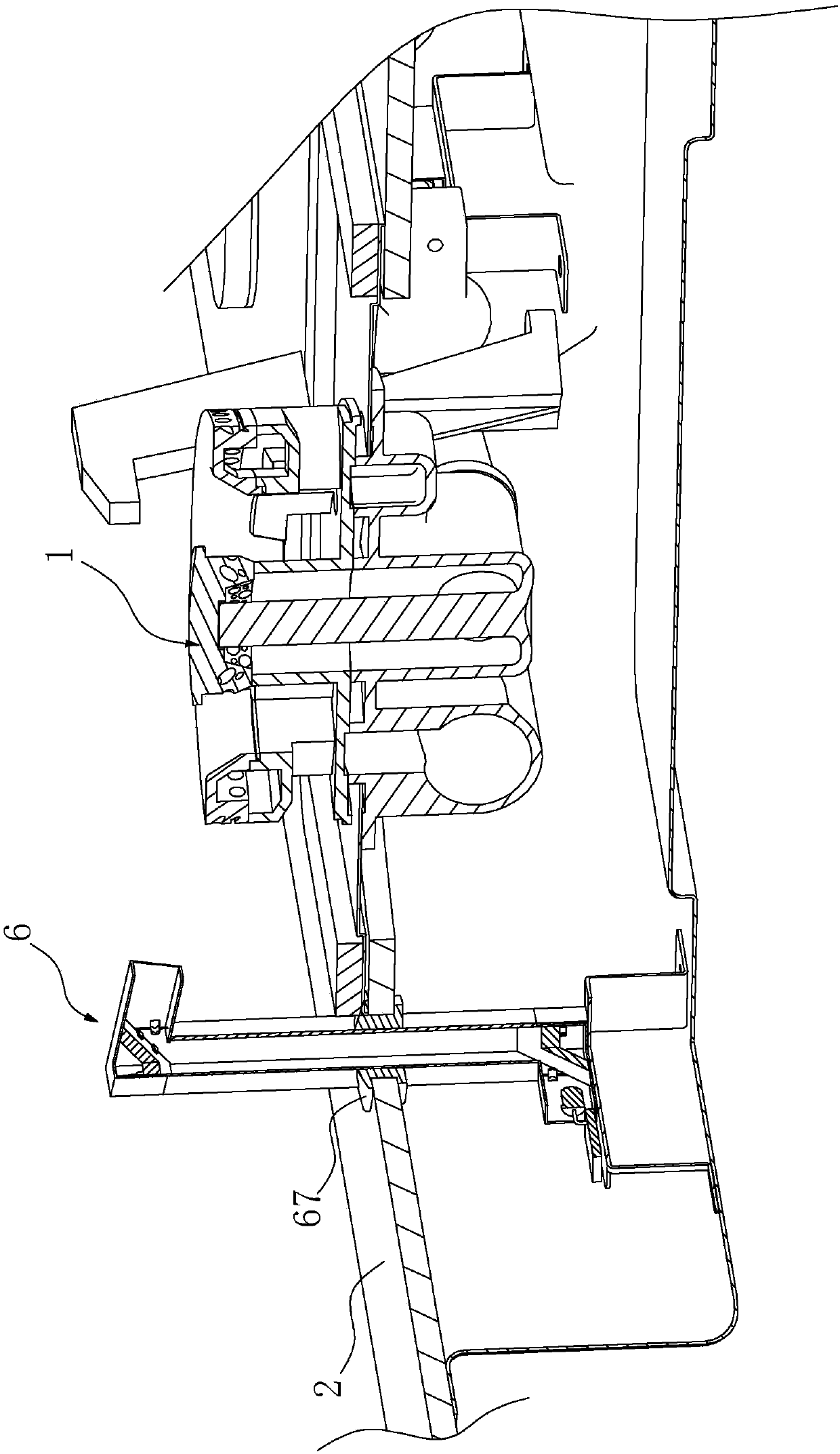
[0030] Such as Figure 2-Figure 7 Shown is the second embodiment of the sensing device used in the flameout protection mechanism of the gas stove according to the present invention. The difference between the sensing device of this embodiment and the first embodiment above is that:
[0031] The daylighting tube 61 includes an upper tube 611, a middle tube 612, and a lower tube 613 which are sequentially connected to form a "Z" shape structure, and an oblique first reflector is arranged at the inner corner where the upper tube 611 and the middle tube 612 are connected. 63. An oblique second reflector 64 is arranged at the inner corner where the middle cylinder 612 and the lower cylinder 613 are connected to form a periscope optical path structure. The ultraviolet photosensitive tube 62 is located in the lower cylinder 613 and faces the second reflection The mirror 64 is located on the optical path of the periscope.
[0032] The first reflection mirror 63 and the second reflec...
PUM
 Abstract
Description
Claims
Application Information
 - R&D
- Intellectual Property
- Life Sciences
- Materials
- Tech Scout
- Unparalleled Data Quality
- Higher Quality Content
- 60% Fewer Hallucinations
Browse by: Latest US Patents, China's latest patents, Technical Efficacy Thesaurus, Application Domain, Technology Topic, Popular Technical Reports.
© 2025 PatSnap. All rights reserved.Legal|Privacy policy|Modern Slavery Act Transparency Statement|Sitemap|About US| Contact US: help@patsnap.com


