Quality detecting device and method based on IC bonding wire

A technology of bonding wire and detection device, which is applied in the direction of measurement device, measurement of electricity, measurement of electric variables, etc., can solve the problem of no longer applicable to quality detection of bonding wire and so on.

Active Publication Date: 2019-07-05
深圳市大族封测科技股份有限公司
View PDF8 Cites 2 Cited by
  • Summary
  • Abstract
  • Description
  • Claims
  • Application Information

AI Technical Summary

Problems solved by technology

[0005] The main purpose of the present invention is to propose a quality detection device and method based on IC bonding wires to solve the problem that traditional DC detection is no longer applicable to the bonding wire quality detection of IC high-speed wire bonding machines

Method used


Image

  • Quality detecting device and method based on IC bonding wire
  • Quality detecting device and method based on IC bonding wire
  • Quality detecting device and method based on IC bonding wire

Examples


Embodiment 1

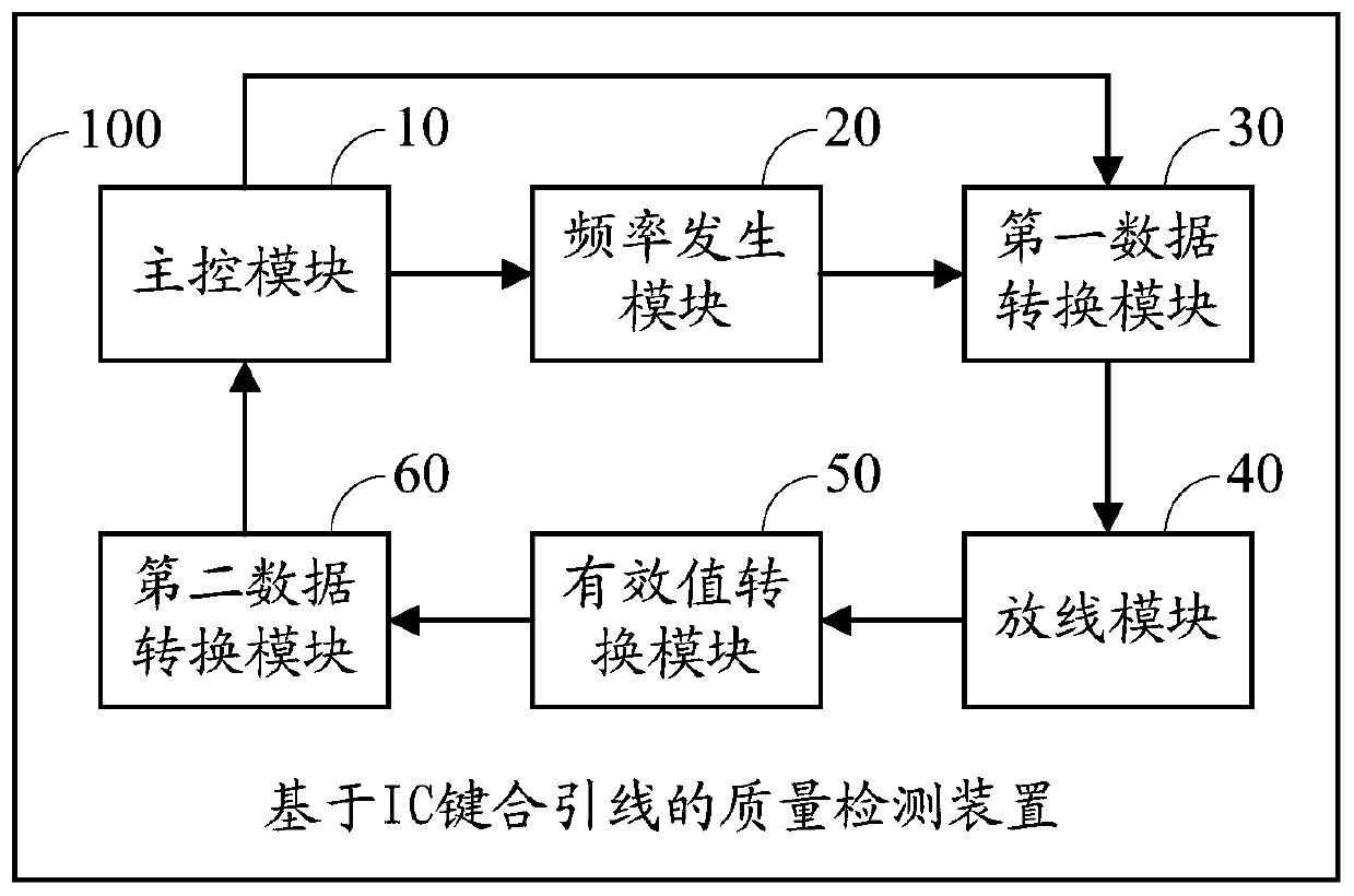
[0050] like figure 1 As shown, the embodiment of the present invention provides an IC-based bonding wire quality detection device 100 for detecting the quality of IC-based bonding wires. The quality inspection device 100 based on IC bonding wires includes but not limited to: a main control module 10 , a frequency generation module 20 , a first data conversion module 30 , a pay-off module 40 , an effective value conversion module 50 and a second data conversion module 60 .

[0051] In the embodiment of the present invention, the connection relationship of the above modules is as follows:

[0052] The main control module 10, the frequency generation module 20, the first data conversion module 30, the pay-off module 40, the effective value conversion module 50 and the second data conversion module 60 are connected end to end in sequence, and the main control module 10 is also connected with the first data conversion module 30 Connection; the main control module 10 controls the f...

Embodiment 2

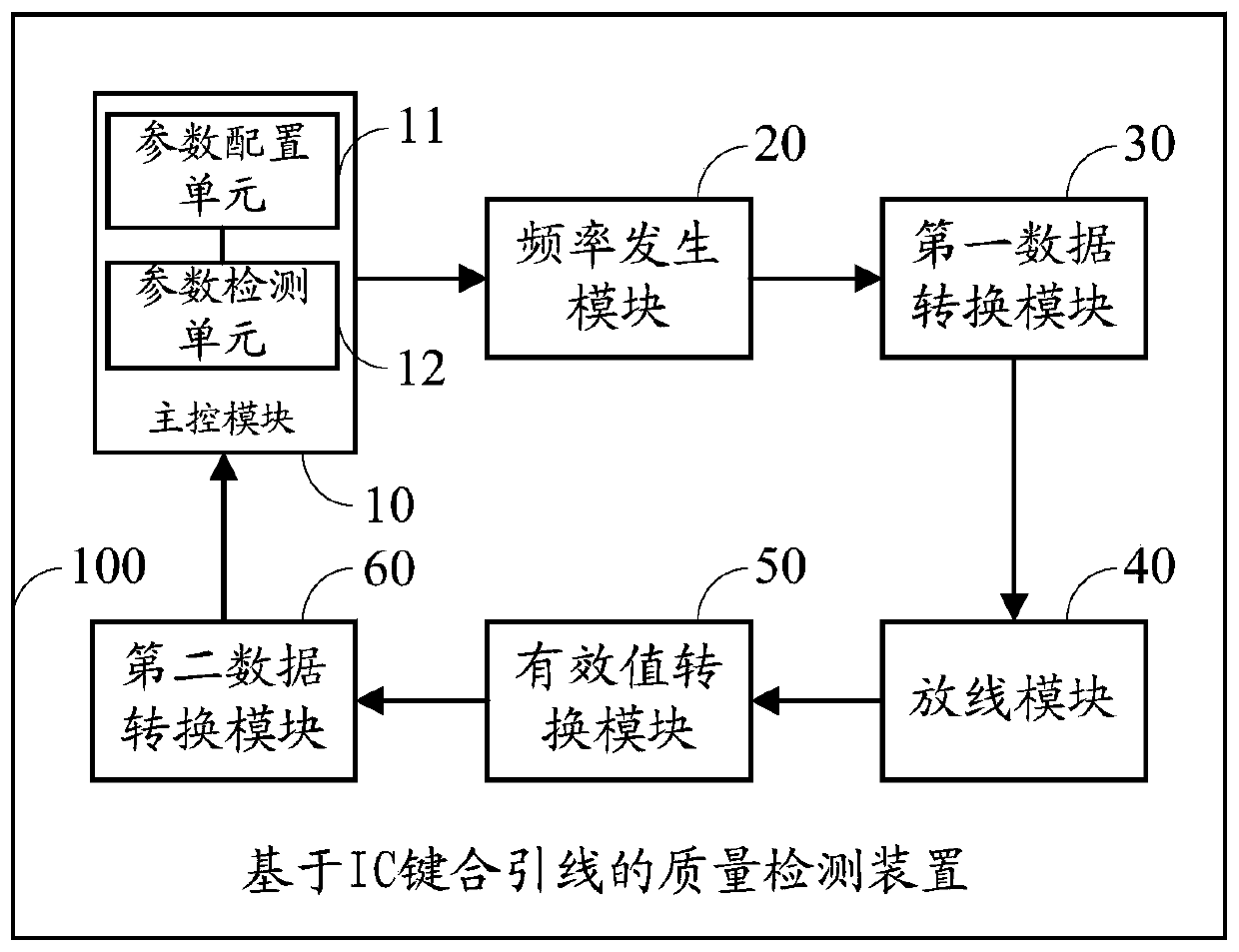
[0076] like figure 2 As shown, the main control module 10 in the first embodiment includes a parameter configuration unit 11 .

[0077] The parameter configuration unit 11 is used to adjust the parameter configuration of the main control module according to the working frequency of the IC, and control the frequency signal output by the frequency generation module and the amplitude of the AC signal output by the first data conversion module.

[0078] In a specific application, the frequency generation module can generate different frequency signals according to different parameter configurations of the main control module. In the embodiment of the present invention, by configuring the parameter configuration of the main control module, the output quantity of one of the input and output ports is changed, so that the frequency signal output by the frequency generation module is suitable for the current operating frequency of the IC. Then use this frequency signal as the referen...

Embodiment 3

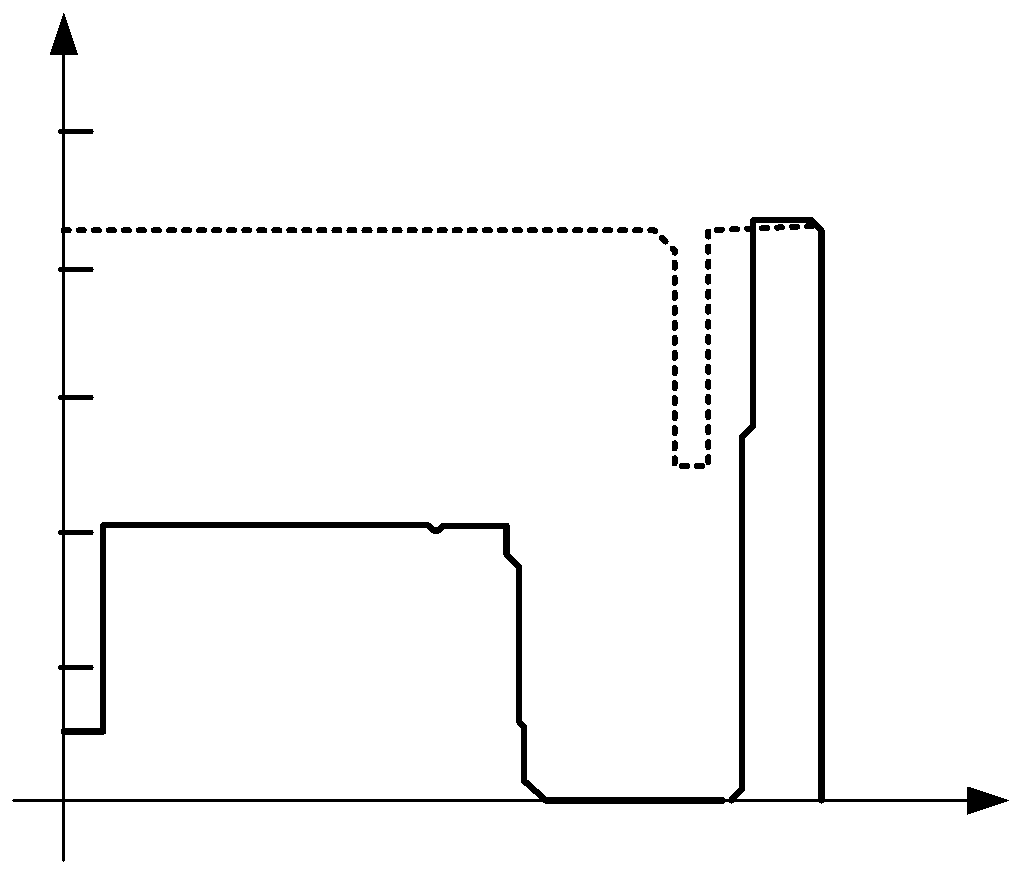
[0085] In the embodiment of the present invention, through the quality inspection device based on the IC bonding wire in the first embodiment above, the obtained quality inspection results of the IC bonding wire include: the first welding inspection result, the wire tail inspection result and the second Weld inspection results.

[0086] Wherein, when the pay-off module places the first welding spot, the main control module outputs the first welding detection result.

[0087] After placing the first solder joint in the pay-off module, when leaving the end of the line, the main control module outputs the detection result of the end of the line;

[0088] After the second welding spot is placed by the pay-off module, when the wire is broken, the main control module outputs the second welding detection result.

[0089] In one embodiment, the quality inspection device based on IC bonding wires further includes a display module.

[0090] Wherein, the display module is connected wit...


PUM


Abstract

The invention is suitable for the semiconductor packaging industrial technology field and provides a quality detecting device based on an IC bonding wire. The device comprises a main control module, afrequency generation module, a first data conversion module, a pay-off module, an effective value conversion module and a second data conversion module. The main control module, the frequency generation module, the first data conversion module, the pay-off module, the effective value conversion module and the second data conversion module are successively connected in a head-to-tail mode. The main control module is connected to the first data conversion module. One end of the pay-off module is connected to the effective value conversion module through a lead line and the other end of the pay-off module is connected to an electrode of IC so as to form a detection closed loop. In the invention, a welding process of each line of the IC can be monitored in real time, a problem of IC functionfailure due to lead failure in the IC is avoided, and detection accuracy is increased and circuit power consumption is reduced compared with those of direct current detection.

Description

technical field [0001] The invention relates to the semiconductor packaging industry, in particular to a quality detection device and method based on IC bonding wires. Background technique [0002] Bonding wire is a manufacturing process based on IC (Integrated Circuit, integrated circuit) chip design. It mainly uses thin metal wires, and uses heat, pressure, and ultrasonic energy to closely weld the metal wires and substrate pads to achieve chip and substrate bonding. Electrical interconnection between chips and information exchange between chips. Under ideally controlled conditions, electron sharing or interdiffusion of atoms occurs between the lead and the substrate, enabling atomic-scale bonding between the two metals. However, in practical applications, the metal leads and the substrate pads are not necessarily tightly welded, and there may be arc welding, disconnection, and the like. Therefore, in the process of completing the bonding wire on the IC, it is very impor...

Claims


Application Information

Patent Timeline
Patent Type & Authority Applications(China)
IPC IPC(8): G01R31/28G01R31/02
CPCG01R31/2853G01R31/2896G01R31/50
Inventor 梁付根李宝平朱绍德高云峰
Owner 深圳市大族封测科技股份有限公司
Why Eureka
Try Eureka