
Direct current brushless motor, robot and method for detecting rotating speed of direct current brushless motor

A technology of brushless DC motor and zero-crossing detection circuit, which is applied in the field of brushless DC motor, robot, and detecting the speed of brushless DC motor. problem, to achieve the effect of increasing the signal frequency, smoothing the speed control, and reducing the time of the speed closed-loop

Pending Publication Date: 2019-07-05
UBTECH ROBOTICS CORP LTD
View PDF0 Cites 2 Cited by
  • Summary
  • Abstract
  • Description
  • Claims
  • Application Information

AI Technical Summary

Problems solved by technology

However, when the motor is running at a low speed, the period of the Hall signal transition becomes longer, resulting in a longer time for speed feedback, which will cause a delay in the output of the speed closed-loop control, resulting in the motor running at low speeds. reduce

Method used


Image

  • Direct current brushless motor, robot and method for detecting rotating speed of direct current brushless motor
  • Direct current brushless motor, robot and method for detecting rotating speed of direct current brushless motor
  • Direct current brushless motor, robot and method for detecting rotating speed of direct current brushless motor

Examples


Embodiment Construction

[0017] The following will clearly and completely describe the technical solutions in the embodiments of the present application with reference to the drawings in the embodiments of the present application. Obviously, the described embodiments are only some of the embodiments of the present application, not all of them. Based on the embodiments in this application, all other embodiments obtained by persons of ordinary skill in the art without making creative efforts belong to the scope of protection of this application.

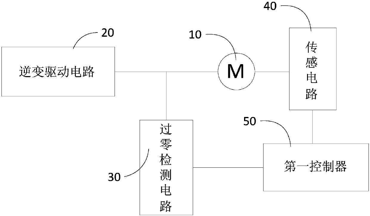
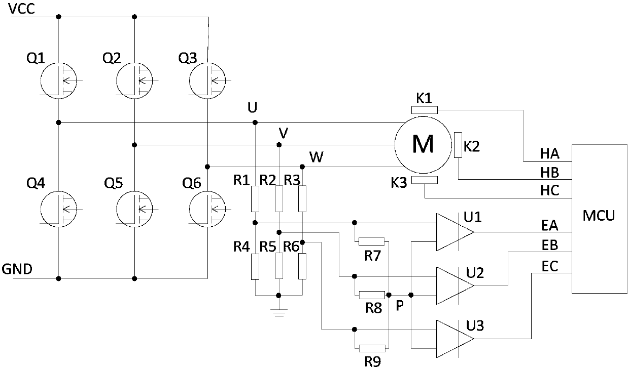
[0018] refer to figure 1 , a schematic structural diagram of an embodiment of a brushless DC motor provided by the present application.

[0019] The DC brushless motor includes a stator and a rotor, and also includes an inverter driving circuit 20 , a zero-crossing detection circuit 30 , a sensing circuit 40 and a first controller 50 . Wherein, both the stator and the rotor are arranged in the electrode 10 .

[0020] The inverter driving circuit 20 is electr...


PUM


Abstract

The invention discloses a direct current brushless motor, a robot and a method for detecting the rotating speed of the direct current brushless motor. The direct current brushless motor comprises a stator, a rotor, an inversion driving circuit, a zero-crossing detection circuit, a sensing circuit and a first controller. The inversion driving circuit is electrically coupled to the stator and is used for driving the phase change of the winding of the stator; the zero-crossing detection circuit is electrically coupled between the stator and the inversion driving circuit and is used for detectingthe zero-crossing point of the counter electromotive force of the direct current brushless motor and generating a zero-crossing signal, and the zero-crossing signal is used for representing the position of the rotor; the sensing circuit is used for detecting the position of the rotor and generating a jump signal when the rotor is in phase change; the first controller is electrically coupled with the zero-crossing detection circuit and the sensing circuit, and obtains the rotating speed of the rotor according to the generating time of the zero-crossing signal and the jump signal. In this way, the speed of acquiring the rotating speed of the direct current brushless motor can be accelerated.

Description

technical field [0001] The present application relates to the technical field of motor control, in particular to a DC brushless motor, a robot and a method for detecting the rotational speed of a DC brushless motor. Background technique [0002] Brushless DC motor (BLDCM) generally uses the three-phase Hall signal at the motor end as the speed feedback signal for closed-loop control of the speed. The motor rotates once, and the three-phase Hall has 6 jump signals. The current motor speed can be calculated by measuring the time difference between any two adjacent jump signals. [0003] With this method of measuring speed, when the motor is running at a high speed, the motor performs speed closed-loop control, and the operation is very smooth. However, when the motor is running at a low speed, the period of the Hall signal jump becomes longer, resulting in a longer time for speed feedback, which will cause a delay in the output of the speed closed-loop control, resulting in t...

Claims


Application Information

Patent Timeline
Patent Type & Authority Applications(China)
IPC IPC(8): H02P6/182H02P6/17
CPCH02P6/182H02P6/17H02P2203/03H02P2203/09
Inventor 熊友军赵计高白熹
Owner UBTECH ROBOTICS CORP LTD
Learn More