Polarizing film, protective plate for image display device, and retardation film
A polarizing film and film technology, applied in the direction of optics, optical elements, polarizing elements, etc., can solve the problems of liquid crystal unit degradation, etc., and achieve the effects of reducing reflection, suppressing temperature rise, and suppressing reflection
- Summary
- Abstract
- Description
- Claims
- Application Information
AI Technical Summary
Problems solved by technology
Method used
Image

Examples
Embodiment 1
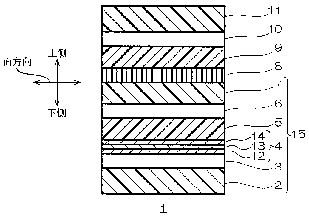
[0214] Such as figure 1 As shown, TAC film (thickness 65 μm, first transparent resin film), acrylic adhesive layer (thickness 23 μm, first adhesive layer), infrared reflection layer, λ / 4 plate (thickness 50 μm, first 1 / 4 wavelength layer), acrylic adhesive layer (thickness 23 μm, third adhesive layer), TAC film (thickness 40 μm, second transparent resin film), polarizer (thickness 22 μm, iodine-impregnated PVA), λ / 4 plate (thickness 50 μm, second 1 / 4 wavelength layer), acrylic adhesive layer (thickness 23 μm, fourth adhesive layer), TAC film containing ultraviolet absorber (thickness 60 μm, third transparent resin film ) were laminated so as to be arranged in order from the bottom to produce the polarizing film of the example.
[0215] It should be noted that as the infrared reflection layer, amorphous ITO (thickness 40nm, first inorganic oxide layer), silver-copper alloy (thickness 8nm, metal layer) and amorphous ITO (thickness 40nm, second inorganic oxide layer) were use...
Embodiment 2
[0218] Except having changed the thickness of the metal layer of an infrared reflection layer into 12 nm, it carried out similarly to Example 1, and produced the polarizing film and the protective plate for image display apparatuses.
Embodiment 3
[0220] Except having changed the thickness of the metal layer of an infrared reflection layer into 20 nm, it carried out similarly to Example 1, and produced the polarizing film and the protective plate for image display apparatuses.
PUM
| Property | Measurement | Unit |
|---|---|---|
| Thickness | aaaaa | aaaaa |
| Moisture permeability | aaaaa | aaaaa |
| Thickness | aaaaa | aaaaa |
Abstract
Description
Claims
Application Information
 - Generate Ideas
- Intellectual Property
- Life Sciences
- Materials
- Tech Scout
- Unparalleled Data Quality
- Higher Quality Content
- 60% Fewer Hallucinations
Browse by: Latest US Patents, China's latest patents, Technical Efficacy Thesaurus, Application Domain, Technology Topic, Popular Technical Reports.
© 2025 PatSnap. All rights reserved.Legal|Privacy policy|Modern Slavery Act Transparency Statement|Sitemap|About US| Contact US: help@patsnap.com