Adsorption and in-situ desorption and regeneration equipment and method for volatile organic compounds

A volatile organic compound and desorption technology, applied in separation methods, chemical instruments and methods, gas treatment, etc., can solve the problems of secondary pollution of dry waste gas and condensed waste water, long cooling time, large water vapor consumption, etc. The effect of complete recovery of adsorption performance, complete regeneration of adsorbent, and shortening of desorption time

Pending Publication Date: 2019-07-09
上海一飒环保工程科技有限公司
View PDF0 Cites 3 Cited by
  • Summary
  • Abstract
  • Description
  • Claims
  • Application Information

AI Technical Summary

Problems solved by technology

[0003] However, the adsorbent in the above desorption process has the following disadvantages due to the desorption under normal pressure and the stripping gas is directly discharged:
[0004] (1) Large water vapor consumption and long desorption time;
[0005] (2) The

Method used


Image

  • Adsorption and in-situ desorption and regeneration equipment and method for volatile organic compounds
  • Adsorption and in-situ desorption and regeneration equipment and method for volatile organic compounds
  • Adsorption and in-situ desorption and regeneration equipment and method for volatile organic compounds

Examples


Example Embodiment

[0031] Example 1

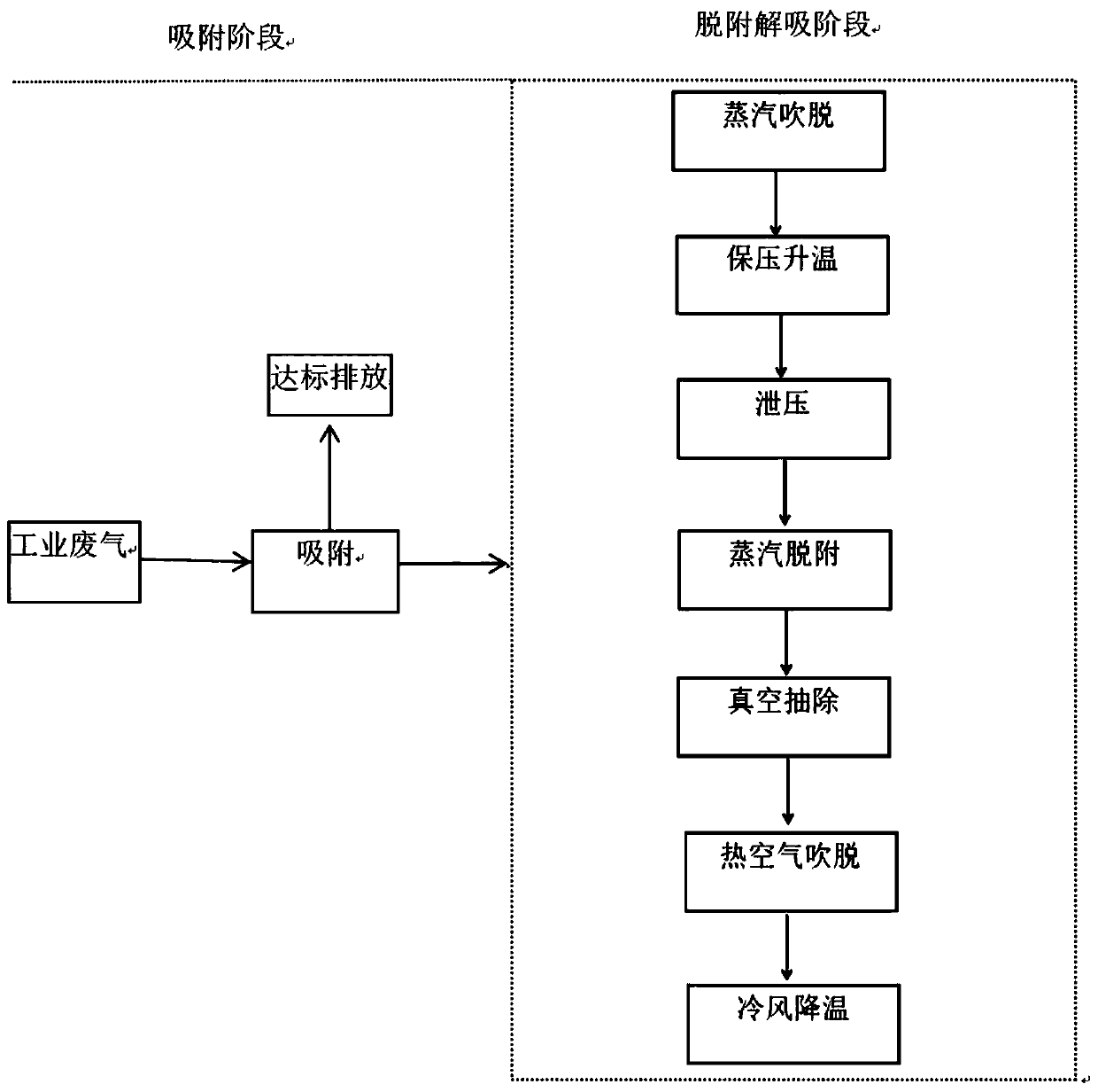
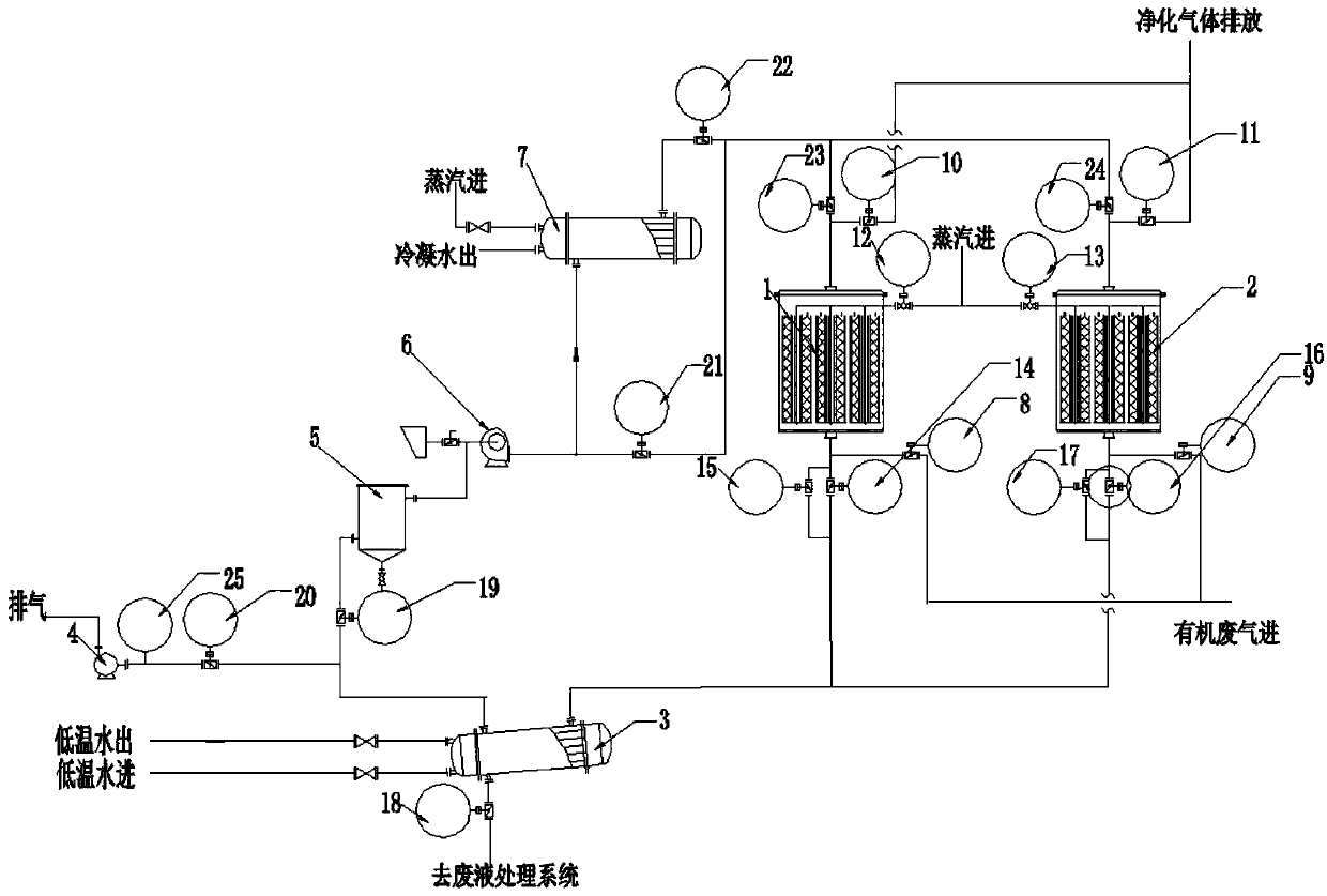
[0032] see figure 2 , a method for adsorption and in-situ desorption regeneration of volatile organic compounds. At this time, the left adsorber 1 is in the adsorption stage, and the right adsorber 2 is in the desorption and desorption stage. The specific steps are as follows:

[0033] 1) Adsorption stage: open the first left valve 8, pass the organic waste gas to be treated into the left adsorber 1, in the left adsorber 1, the organic waste gas is adsorbed by the adsorbent, and open the second left valve 10 to treat the waste gas The gas is discharged to the exhaust cylinder through the exhaust pipe of the left adsorber 1. After the adsorbent in the left adsorber 1 is saturated or according to the process setting requirements, it is switched to the right adsorber 2 for continuous adsorption;

[0034] 2) Desorption and desorption stage: Desorption and desorption adopts a seven-step method, including steam blowing off, pressure maintaining and heating, pres...

Example Embodiment

[0042] Example 2

[0043] see figure 2 , a method for adsorption and in-situ desorption regeneration of volatile organic compounds. At this time, the left adsorber 1 is in the adsorption stage, and the right adsorber 2 is in the desorption and desorption stage. The specific steps are as follows:

[0044] 1) Adsorption stage: open the first right valve 9, and pass the organic waste gas to be treated into the right adsorber 2, where the organic waste gas is adsorbed by the adsorbent in the right adsorber 2, and the treated gas passes through the right adsorber 2 Open the second left valve 10 to discharge to the exhaust pipe, after the adsorbent in the right adsorber 2 is saturated or according to the process setting requirements, switch to the left adsorber 1 for continuous adsorption;

[0045] 2) Desorption and desorption stage: Desorption and desorption adopts a seven-step method, including steam blowing off, pressure maintaining and heating, pressure relief, steam desorptio...


PUM


Abstract

The invention discloses adsorption and in-situ desorption and regeneration equipment for volatile organic compounds. The adsorption and in-situ desorption and regeneration equipment comprises a left adsorption device, a right adsorption device, a condenser, a vacuum pump, a demister, a drying draught fan and a heater, wherein an organic waste gas pipeline inlet is connected with the left adsorption device and the right adsorption device through a first left valve and a first right valve respectively; the upper ends of the left adsorption device and the right adsorption device are connected with an exhausting barrel through a second left valve and a second right valve respectively; a steam pipeline inlet is connected with the left adsorption device and the right adsorption device through asixth left valve and a sixth right valve respectively. By adopting the adsorption and in-situ desorption and regeneration equipment, internal circulation of dry gas is realized; after being purified,the dry gas is discharged and secondary pollution is not caused; rapid desorption can be carried out in a desorption process, the utilization amount of high-temperature steam is reduced and the desorption time is shortened; an adsorbent is completely regenerated and the adsorption performance is completely recovered; and the drying time and the cooling time are shortened and energy saving and consumption reduction are realized.

Description

technical field [0001] The invention relates to the technical field of adsorption treatment, in particular to a device and method for adsorption and in-situ desorption regeneration of volatile organic compounds. Background technique [0002] In the existing adsorption-desorption process, the desorption process adopts a "two-step method", that is, steam desorption and air blowing. During steam desorption, high-temperature steam is introduced from the steam pipeline, from the inside to the outside / side The adsorbent core is purged to the other side, and the generated condensate and non-condensable gas are respectively discharged from the condensate pipeline and the desorbed product pipeline into the waste liquid treatment system for treatment; when the air is blown off, the drying fan is started to deplete the adsorption The adsorbent in the device is dried to reduce moisture and restore the adsorption performance of the adsorbent. After the blow-off is completed, stop the dry...

Claims


Application Information

Patent Timeline
IPC IPC(8): B01D53/02
CPCB01D53/02B01D2257/70B01D2259/40086Y02A50/20
Inventor 刘学军李帅耿彦勇
Owner 上海一飒环保工程科技有限公司
Why Eureka
Try Eureka