Efficient polishing device for high-speed steel

A high-speed steel, high-efficiency technology, applied in the direction of grinding/polishing safety devices, grinding machines, grinding/polishing equipment, etc., can solve the problems of low grinding efficiency, inconvenient operation table to move workpieces, uneven grinding, etc., and achieve good heat dissipation effect Effect

Pending Publication Date: 2019-07-09
WANSHITAI METAL IND KUNSHAN
View PDF0 Cites 1 Cited by
  • Summary
  • Abstract
  • Description
  • Claims
  • Application Information

AI Technical Summary

Problems solved by technology

[0005] In order to solve the existing grinding device for high-speed steel existing in the background technology, the grinding is uneven and the grinding efficiency is low. At the same time, the operating table where the workpiece is placed is not convenient for translating the workpiece, and it is troublesome when grinding; The technical problem that the heat accumulation of the grinding machine head affects the service life. The invention proposes a high-efficiency grinding device for high-speed steel. The invention has stable clamping and reduces shaking during work; at the same time, the heat dissipation is better, and the whole device is dissipated through the air outlet. , the drive motor can be locally dissipated through heat conduction parts, and the grinding head can also be locally dissipated through the cooperation of the air duct and the guide tube. The air duct is a hose that does not affect normal use when the grinding device needs to be moved

Method used


Image

  • Efficient polishing device for high-speed steel
  • Efficient polishing device for high-speed steel
  • Efficient polishing device for high-speed steel

Examples


Embodiment Construction

[0023] In order to make the object, technical solution and advantages of the present invention clearer, the present invention will be further described in detail below in combination with specific embodiments and with reference to the accompanying drawings. It should be understood that these descriptions are exemplary only, and are not intended to limit the scope of the present invention. Also, in the following description, descriptions of well-known structures and techniques are omitted to avoid unnecessarily obscuring the concept of the present invention.

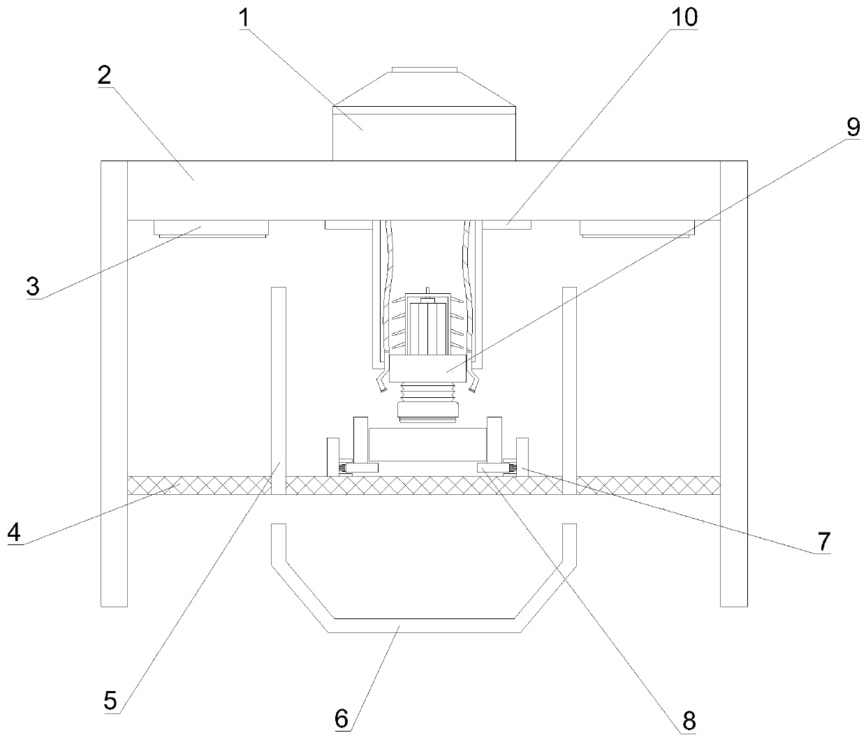
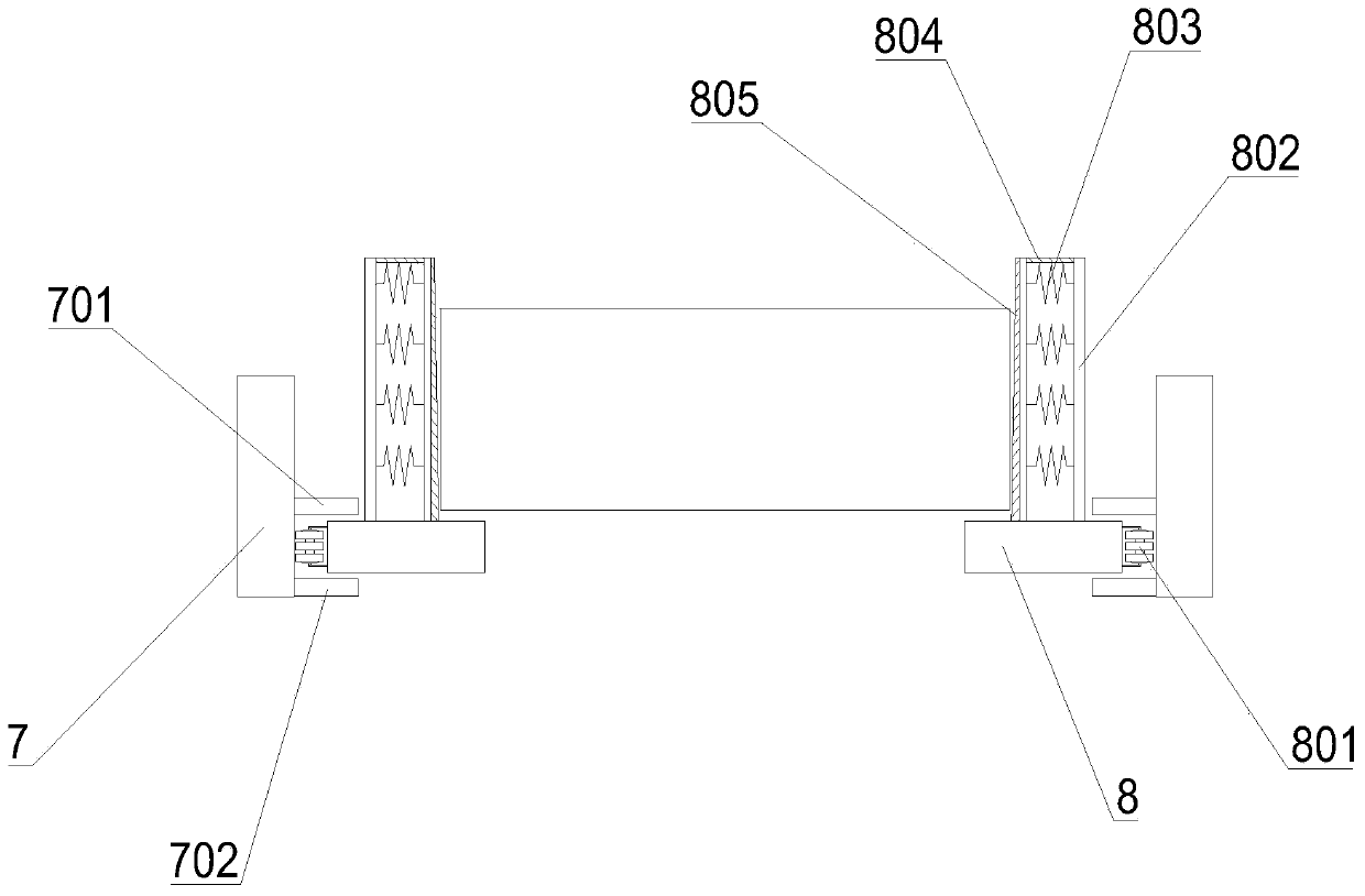
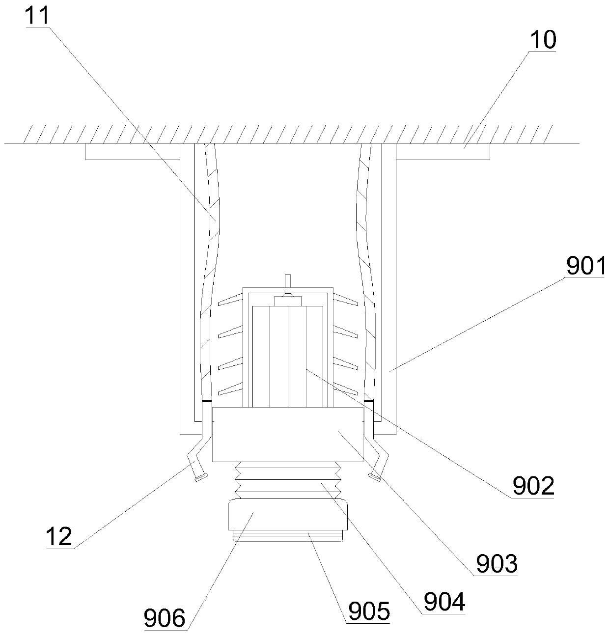
[0024] Such as Figure 1-5 As shown, a high-efficiency grinding device for high-speed steel proposed by the present invention includes a mounting frame 2, a base 4, a blowing device 1, a sliding device 10, a grinding device 9, a fixing frame 7 and a clamp 8;

[0025] The base 4 is arranged on the mounting frame 2; the base 4 is provided with a plurality of steel skeletons 401, and the steel skeleton 401 is preset with a ...


PUM


Abstract

The invention discloses an efficient polishing device for high-speed steel. The efficient polishing device comprises an installing frame, a base, an air blowing device, sliding devices, a polishing device body, fixing frames and fixtures; the base is arranged on the installing frame, a plurality of steel skeletons are arranged on the base, a plurality of installing holes are reserved in the steelskeletons, and the fixing frames and the installing holes are installed in a matched mode; pulley sets are arranged on the fixtures; vertical pillars are arranged on the fixtures, a plurality of elastic pieces are arranged in the vertical pillars, and sealing plates are arranged at the tops of the vertical pillars; the installing seat is arranged on the polishing device, a plurality of telescopicrods are arranged on two sides of the installing seat, and the tops of the telescopic rods are connected with the sliding devices; a driving motor is arranged on the installing seat, and a transmission shaft is arranged on the driving motor; a protecting shell is arranged on the outer part of a polishing machine head; a sleeve rods are arranged on the protecting shell; and the air blowing device is arranged at the top of the installing frame, and a plurality of air outlets are formed in the installing frame. According to the efficient polishing device for the high-speed steel, clamping is stable, shaking generated during working is reduced; and meanwhile, thermal dissipation is good, and the integrity and part of the device can be subjected to thermal dissipation correspondingly.

Description

technical field [0001] The invention relates to the technical field of grinding devices, in particular to an efficient grinding device for high-speed steel. Background technique [0002] High-speed steel (HSS) is a tool steel with high hardness, high wear resistance and high heat resistance, also known as high-speed tool steel or front steel, commonly known as white steel; high-speed steel has good process performance, good strength and toughness , so it is mainly used to manufacture complex thin blades and impact-resistant metal cutting tools, as well as high-temperature bearings and cold extrusion dies. In addition to the high-speed steel produced by the smelting method, powder metallurgy high-speed steel appeared after the 1960s. Its advantage is that it avoids the reduction of mechanical properties and heat treatment deformation caused by the carbide segregation caused by the smelting method; prior art Among them, the existing grinding device for high-speed steel is not...

Claims


Application Information

Patent Timeline
Patent Type & Authority Applications(China)
IPC IPC(8): B24B19/00B24B55/02B24B55/06
CPCB24B19/00B24B55/02B24B55/06
Inventor 孙启毅徐真真高娟娟徐恩燕朱晓军
Owner WANSHITAI METAL IND KUNSHAN
Why Eureka
Try Eureka