Roadbed pile pipe curtain supporting structure after addition of two-line-platform to railway

A second-line platform and curtain technology, applied in infrastructure engineering, roads, excavation, etc., can solve the problems of land occupation, increase in filling (excavation) volume investment, low construction efficiency, and high construction risk, so as to ensure normal operation and safety, reduce the support structure, and reduce the construction risk

Pending Publication Date: 2019-07-09
新疆铁道勘察设计院有限公司
View PDF0 Cites 3 Cited by
  • Summary
  • Abstract
  • Description
  • Claims
  • Application Information

AI Technical Summary

Problems solved by technology

However, the large-scale seamless line cutting (connection) operation will cause damage to the existing line and cannot be restored to its original state
[0007] (2) When erecting 3-5-3 buckle hanging rail beams on existing railways, the railway line needs to be slow-moving at a speed limit, which makes the existing railway transportation capacity more tense, and generally does not have the conditions for long-term, multi-frequency speed-limited construction
The manual excavation piles used are basically located close to the existing railway shoulders. There are a large number of them and they are buried deep (often encountering groundwater). The process is basically completed by manpower, the construction efficiency is low, the safety is poor, and the investment is high
In the actual operation process, the normal operation and safety of the existing railway cannot be absolutely guaranteed, and the construction risk is very high
[0009] (4) The installation of pile-slab continuous walls between the existing line and the new second line will increase the line spacing, and the area of ​​the second line, filling (excavation) volume, investment, etc. will also increase accordingly

Method used


Image

  • Roadbed pile pipe curtain supporting structure after addition of two-line-platform to railway
  • Roadbed pile pipe curtain supporting structure after addition of two-line-platform to railway
  • Roadbed pile pipe curtain supporting structure after addition of two-line-platform to railway

Examples


Embodiment Construction

[0029] In order to make the object, technical solution and advantages of the present invention clearer, the present invention will be further described in detail below in conjunction with the accompanying drawings and embodiments.

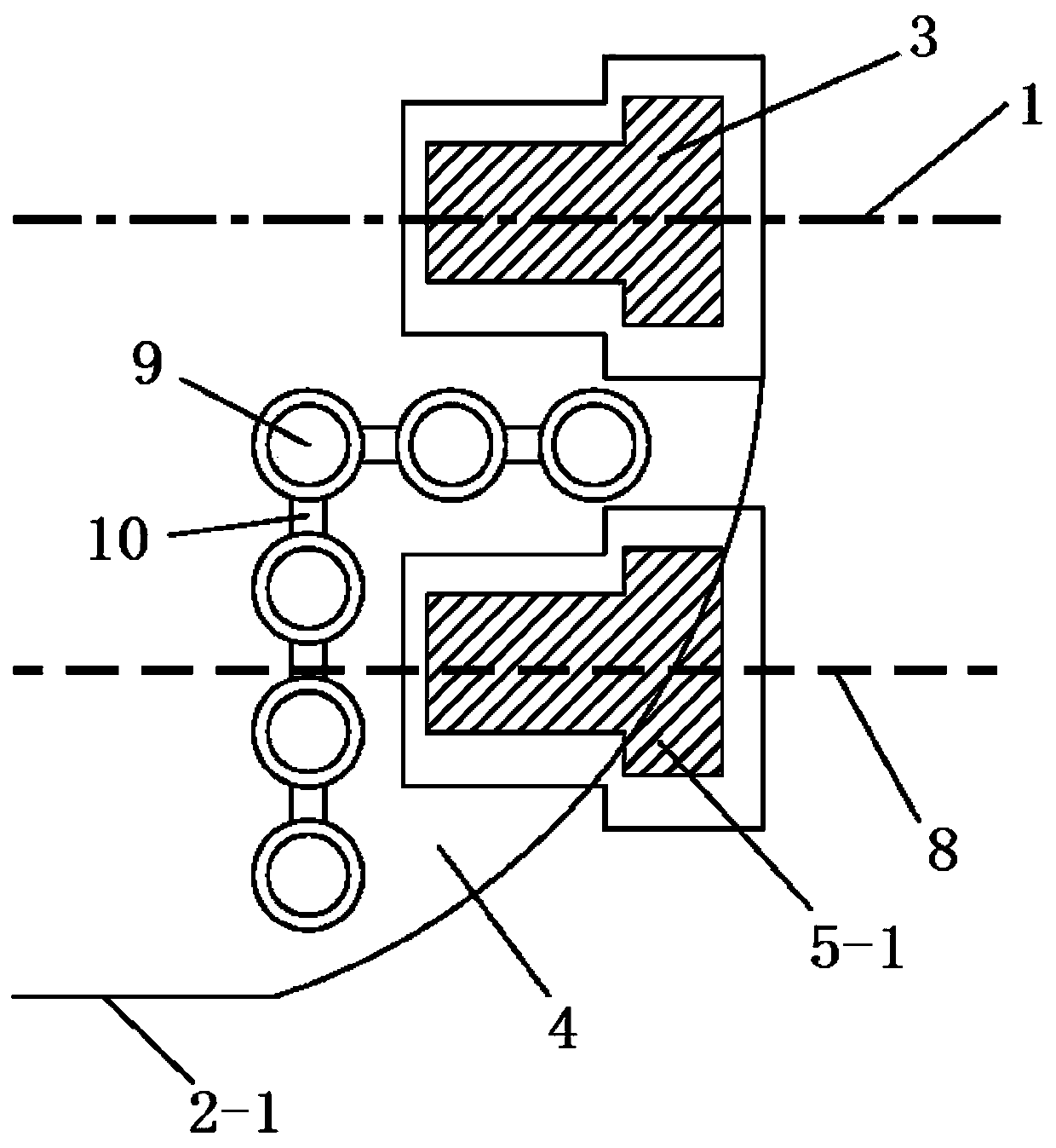
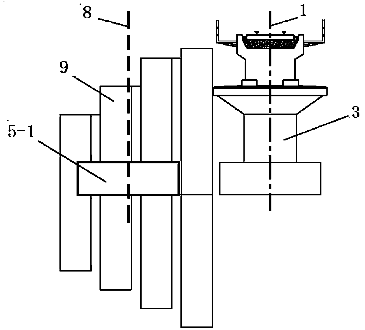
[0030] At present, the conventional protection schemes for the excavation of the foundation pit of the newly added second-line abutment include: the existing railway lines within the construction scope shall be protected by "erecting 3-5-3 buckle hanging rail beams", and the second-line abutment 5-1 shall rely on the existing The abutment 3 and the slope of the foundation pit on one side of the subgrade are protected by "multiple excavated piles 9 plus cast-in-place reinforced concrete walls 10" (referred to as "pile-slab continuous wall"). The gap between piles 9 and 9 is cast-in-place Reinforced concrete wall 10 (thickness 20cm) is used for secondary protection, and woven bag cofferdam is used to protect the slope toe. figure 1 , figure 2 Shown...


PUM


Abstract

The invention discloses a roadbed pile pipe curtain supporting structure after addition of a two-line-platform to a railway, and the supporting structure is a vertical excavation supporting system formed by a horizontal steel pipe curtain and a soil blocking plate with newly-added supporting piles at the back of an existing bridge abutment or at a road shoulder position behind the bridge abutmentand newly-added supporting piles at a slope toe position of an existing railway roadbed as supporting points. The structure is composed of an existing bridge abutment, the supporting piles, the horizontal steel pipe curtain, the soil blocking plate and the like. The structure is safe and convenient, supporting is not prone to losing stability or causing collapse, operation of an existing railway is not affected, and normal operation and safety of the existing railway can be guaranteed. In addition, the foundation pit supporting structure is novel, fewer materials are used on the basis that safety is guaranteed, cost is saved, the mechanical construction efficiency is higher, and the line spacing can be reduced to a maximum extent.

Description

technical field [0001] The invention relates to the technical field of roadbed support construction, in particular to a curtain support structure of roadbed pile tubes behind a newly added second-line railway abutment. Background technique [0002] With the deepening of reform and opening up and the adjustment of the economic and industrial structure, transportation enterprises have shown unprecedented vitality, and various transportation methods have developed rapidly. As the main artery of the national economy, the railway is also the most popular means of transportation. It has the characteristics and advantages of high transport capacity, long distance, low cost, less land occupation, all-weather, energy saving, and low pollution. It plays a pivotal role in the national economy. Location. [0003] With the continuous increase of the amount of goods transported by railways, when the capacity of existing railways is saturated or is about to be saturated, it is necessary t...

Claims


Application Information

Patent Timeline
Patent Type & Authority Applications(China)
IPC IPC(8): E02D17/04E01B2/00
CPCE02D17/04E01B2/006E02D2300/0029E02D2300/002E02D2250/003Y02A30/60
Inventor 努尔买买提·吐尔逊张树新张振钛庄新玉江华韦朝王振文
Owner 新疆铁道勘察设计院有限公司
Why Eureka
Try Eureka