
A detection and closed-loop control system and control method of interferometric fiber optic gyroscope loop gain

A technology of fiber optic gyroscope and loop gain, which is applied in general control system, control/adjustment system, surveying and navigation, etc., and can solve gyroscope zero influence, scale factor change, zero bias stability and random walk coefficient degradation, etc. problem, to achieve the effect of keeping the loop gain stable

Active Publication Date: 2020-01-07
BEIHANG UNIV
View PDF4 Cites 0 Cited by
  • Summary
  • Abstract
  • Description
  • Claims
  • Application Information

AI Technical Summary

Problems solved by technology

The change of the gain of the forward channel will cause the instability of the signal-to-noise ratio of the gyro detection, resulting in the instability of the frequency characteristics of the fiber optic gyroscope and the corresponding bandwidth.
In addition, for the fiber optic gyroscope equipped with a periodic dither signal to suppress the dead zone of the gyroscope, due to the fixed compensation of the additionally applied periodic dither signal, the change of the forward gain will make the compensation of the dither signal inaccurate, which will appear in the output of the fiber optic gyroscope Additional false speed signal due to inaccurate compensation, resulting in deterioration of zero bias stability and random walk coefficient
The change of the gain of the feedback channel will cause reset error, cause additional demodulation error, and affect the zero bias of the gyro; due to the existence of the closed-loop system, the feedback channel determines the proportional coefficient of input and output, that is, the scaling factor; therefore, the feedback channel A change in gain also causes a change in the scale factor

Method used


Image

  • A detection and closed-loop control system and control method of interferometric fiber optic gyroscope loop gain
  • A detection and closed-loop control system and control method of interferometric fiber optic gyroscope loop gain
  • A detection and closed-loop control system and control method of interferometric fiber optic gyroscope loop gain

Examples


Embodiment Construction

[0048]The following will clearly and completely describe the technical solutions in the embodiments of the present application with reference to the accompanying drawings in the embodiments of the present application. Obviously, the described embodiments are only for illustration, and are not intended to limit the present application.

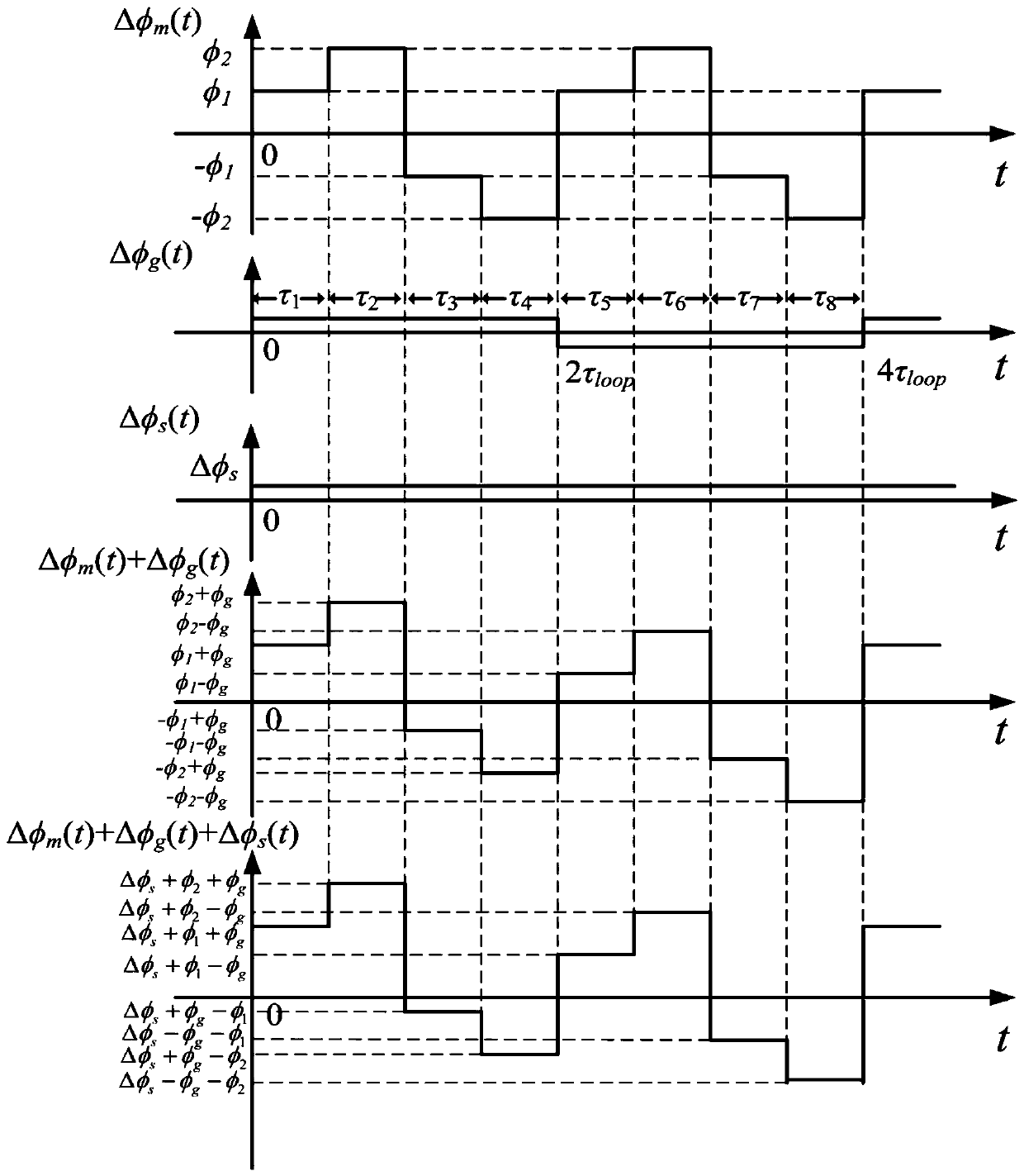
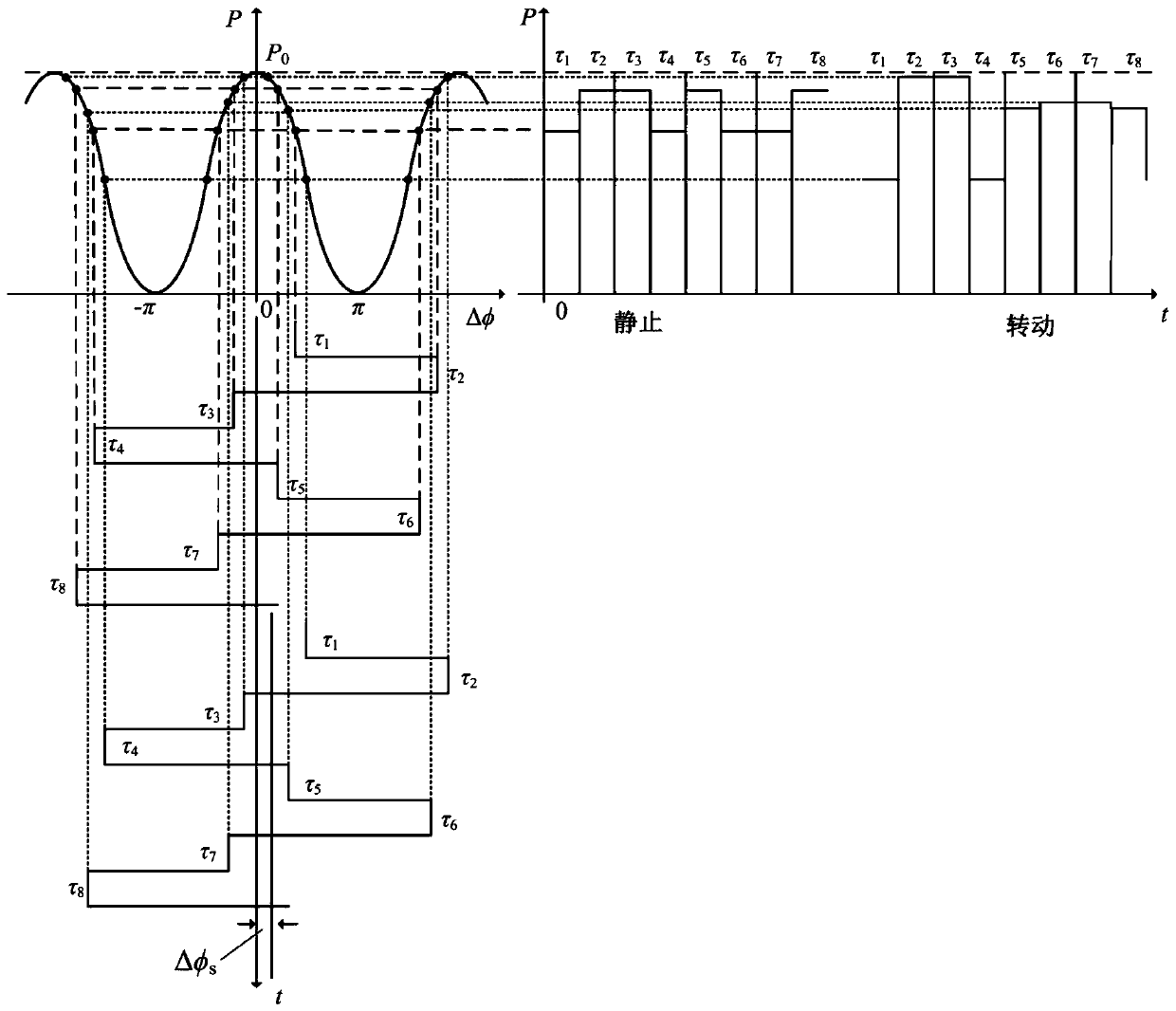
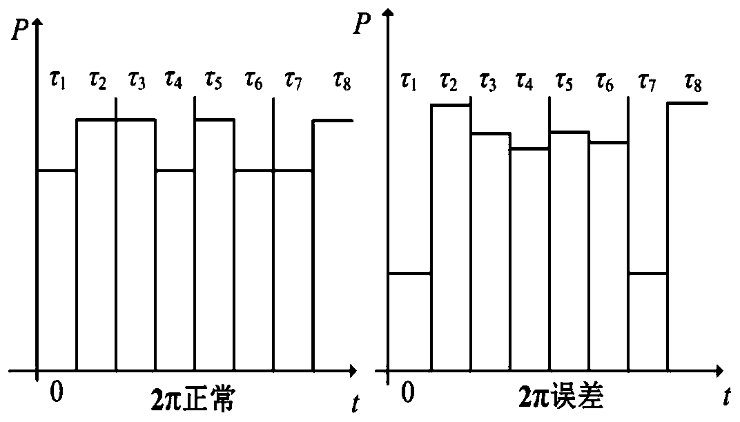
[0049] In order to achieve the gain closed-loop, it is necessary to realize the real-time test of the gain at first. Taking the working state of the four-state modulation as an example, when adding the four-state modulation to the Y waveguide, an additional gain monitoring signal needs to be added. Phase Δφ corresponding to four-state modulation m followed by φ 1 , φ 2 ,-φ 1 ,-φ 2 (When there is no 2π error, φ 1 +φ 2 = 2π, φ 1 2 >π, as φ 1 = 3π / 4, φ 2 =5π / 4), the frequency is the eigenfrequency v of the fiber ring k =1 / (2τ loop ), τ loop is the transit time, which is the time for light to propagate in the fiber ring for one week; th...


PUM


Abstract

The invention discloses a detection and closed-loop control system for a loop gain of an interferometric fiber optic gyroscope. By stabilizing a forward channel gain and a feedback channel gain, stability of the integral loop gain is ensured, and the output characteristics of the fiber optic gyroscope are not influenced; and the system particularly comprises a first loop, a second loop and a gainautomatic control loop, wherein the first loop comprises a forward channel, a feedback channel, a step wave generation module, a modulation signal module and a rate demodulation module; the second loop comprises a forward channel, a feedback channel, a 2pi error demodulation module and a 2pi voltage integrator; and the gain automatic control loop comprises a forward channel, a feedback channel, again detection module, a reference gain module, a gain demodulation module, a gain error integrator and a gain error filter.

Description

technical field [0001] The invention belongs to the field of fiber optic gyroscopes, in particular to a detection and closed-loop control method for the loop gain of an interference type fiber optic gyroscope. Background technique [0002] The fiber optic gyroscope is a fiber optic angular velocity sensor based on the Sagnac effect. The interferometric fiber optic gyroscope has the advantages of no rotating parts, wide accuracy coverage, large dynamic range, and high reliability. It has been widely used in aviation, aerospace, navigation, Weapons, energy and other fields. Interferometric fiber optic gyroscope is the core device of fiber optic inertial navigation system, and its performance plays a decisive role in the navigation accuracy of inertial navigation system. [0003] Fiber optic gyroscope loop gain includes forward channel gain and feedback channel gain. The gain of the forward channel includes the optical power reaching the detector, the gain of the pre-analog a...

Claims


Application Information

Patent Timeline
Patent Type & Authority Patents(China)
IPC IPC(8): G01C19/66G05B13/02
CPCG01C19/66G01C19/661G05B13/024
Inventor 郑月田龙杰张春熹孔令海陈和宇
Owner BEIHANG UNIV
Learn More