Tetrahedral array three-dimensional passive direction finding method for underwater glider
An underwater glider, tetrahedron technology, applied in directions such as direction finders using ultrasonic/sonic/infrasonic waves, systems for determining direction or offset, etc. The effect of the simple direction finding process
- Summary
- Abstract
- Description
- Claims
- Application Information
AI Technical Summary
Problems solved by technology
Method used
Image
Examples
specific Embodiment approach 1
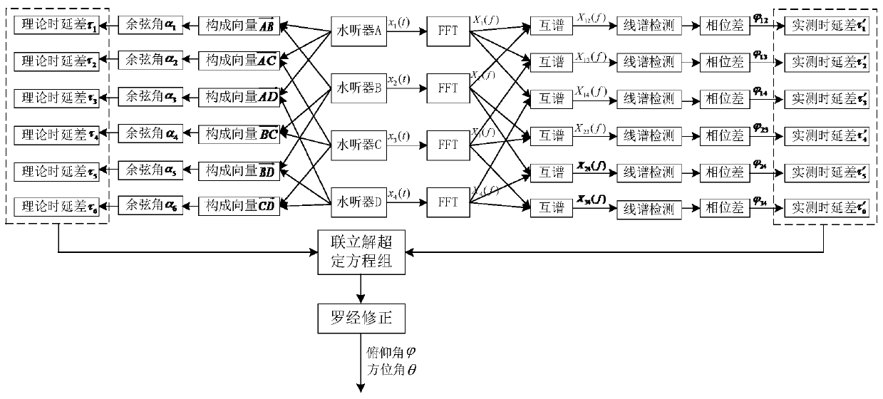
[0030] A kind of underwater glider tetrahedron array three-dimensional passive direction finding method of the present embodiment, described direction finding method is to realize through the following steps:
[0031] Step 1. Combine the four hydrophones A, B, C and D in pairs to obtain the vectors of each combination in the Cartesian coordinate system with Then obtain the obtained vectors and the incident wave direction vector The resulting cosine angle α 1 , α 2 , α 3 , α 4 , α 5 , α 6 ;
[0032] Step 2. Obtain the vectors obtained in step 1 and the direction vector of the incident wave The resulting cosine angle corresponds to the theoretical delay difference τ of the signal arriving at the two hydrophones 1 , τ 2 , τ 3 , τ 4 , τ 5 , τ 6 ;
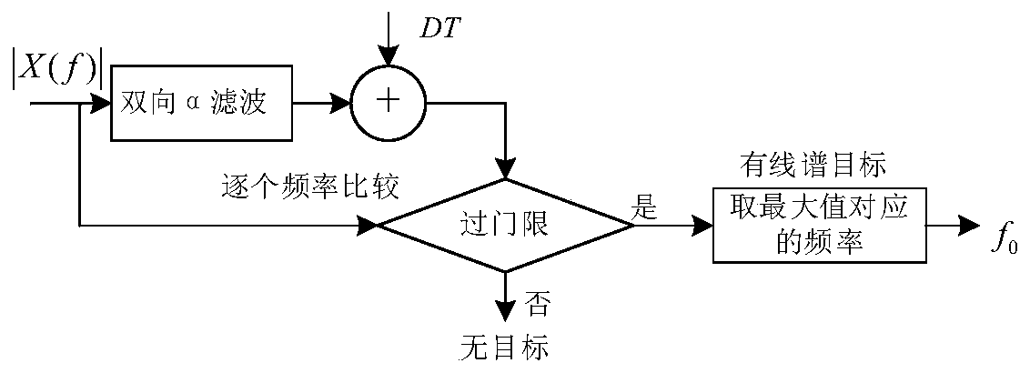
[0033] Step 3, the received signals of four hydrophones are transformed into frequency domain signal X by Fourier transform (FFT) 1 (f), X 2 (f), X 3 (f), X 4 (f), the frequency domain signal is calculated accordi...
specific Embodiment approach 2
[0041] Different from the specific embodiment 1, in the method for three-dimensional passive direction finding of an underwater glider tetrahedral array in this embodiment, in the step 1, the four hydrophones A, B, C and D are combined in pairs , get the vectors of each combination in the Cartesian coordinate system with process, specifically:
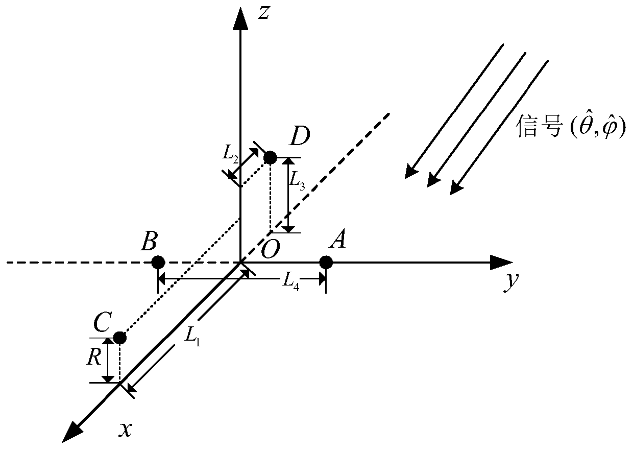
[0042] Step 1-1. Set the underwater glider platform as the carrier to establish a three-dimensional Cartesian coordinate system xyz, which is the carrier coordinate system. The schematic diagram is as follows figure 1 As shown, the positions of the four hydrophones are points A, B, C, D, and L 1 is the vertical distance from No. 3 hydrophone to AB, L 2 is the vertical distance from No. 4 hydrophone to O, L 3 is the vertical distance from the No. 4 hydrophone to the central axis, L 4 is the distance between the two wings AB, R is the radius of Glider, where A and B are located on the y-axis and are symmetrical about the origin, a...
specific Embodiment approach 3
[0056] Different from the second specific embodiment, in the three-dimensional passive direction finding method of an underwater glider tetrahedral array in the present embodiment, in the step 2, the vectors obtained in the step 1 and the incident wave direction vector are obtained The resulting cosine angle corresponds to the theoretical delay difference τ of the signal arriving at the two hydrophones 1 , τ 2 , τ 3 , τ 4 , τ 5 , τ 6 process, specifically:
[0057] Four hydrophones A, B, C, and D form a tetrahedral array, and each hydrophone is used as an array element. The tetrahedral array and the experimental target meet the far-field plane wave condition. The schematic diagram is as follows: figure 2 As shown, between array elements A and B, the angle α between the known incident signal and the line where the array element is located 1 In the case of , the delay difference τ for the signal to reach the two hydrophones A and B 1 for:
[0058]
[0059] where c i...
PUM
 Abstract
Description
Claims
Application Information
 - R&D
- Intellectual Property
- Life Sciences
- Materials
- Tech Scout
- Unparalleled Data Quality
- Higher Quality Content
- 60% Fewer Hallucinations
Browse by: Latest US Patents, China's latest patents, Technical Efficacy Thesaurus, Application Domain, Technology Topic, Popular Technical Reports.
© 2025 PatSnap. All rights reserved.Legal|Privacy policy|Modern Slavery Act Transparency Statement|Sitemap|About US| Contact US: help@patsnap.com


