Supercharge Your Innovation With Domain-Expert AI Agents!

Method for adjusting clearance between HPS medium-speed mill grinding roller and grinding table liner

A technology of grinding rollers and grinding discs, which is applied in the field of gap adjustment between grinding rollers and grinding disc liners of HPS medium-speed grinding. The effect of machine capacity, obvious implementation effect and simple construction

Active Publication Date: 2019-07-12
BAOTOU IRON & STEEL GRP
View PDF7 Cites 0 Cited by
  • Summary
  • Abstract
  • Description
  • Claims
  • Application Information

AI Technical Summary

Problems solved by technology

[0002] After the direct injection system of No. 6 blast furnace was put into operation at the end of 2006, it was found that the medium-speed mill pulverizing system became larger due to the wear and tear of the gap D between the grinding roller and the lining plate of the grinding disc, resulting in a decrease in production capacity and an increase in waste
The whole adjustment time is 7 hours, the working space is narrow and complex, the ambient temperature is high, and it is prone to mechanical strain, gas poisoning and other injuries
During the production process, the gap between the grinding roller and the grinding disc becomes larger, the adjustment frequency is high, and the adjustment time is long, which affects the mill capacity
The maintenance working environment is poor and there are many unsafe factors

Method used


Image

  • Method for adjusting clearance between HPS medium-speed mill grinding roller and grinding table liner
  • Method for adjusting clearance between HPS medium-speed mill grinding roller and grinding table liner

Examples


Embodiment Construction

[0021] In the following, only some exemplary embodiments are briefly described. As those skilled in the art would realize, the described embodiments may be modified in various different ways, all without departing from the spirit or scope of the present invention. Accordingly, the drawings and descriptions are to be regarded as illustrative in nature and not restrictive.

[0022] The present invention will be described in detail below in conjunction with the accompanying drawings and specific embodiments.

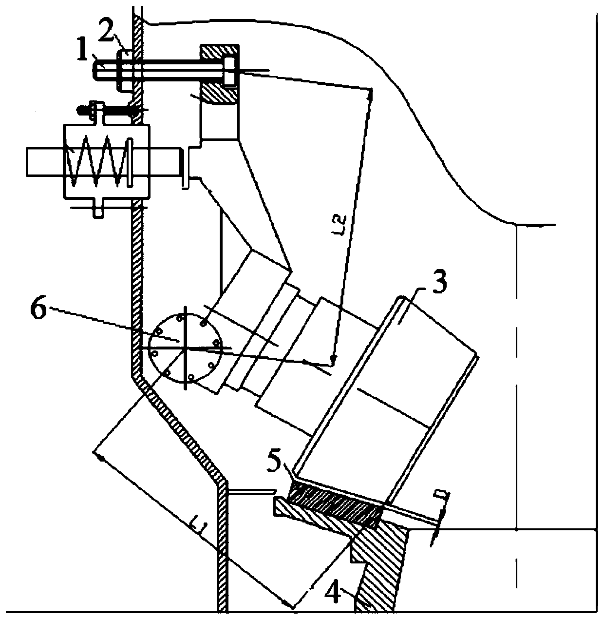
[0023] Such as figure 1 Shown is a schematic diagram of a part of the structure of a medium-speed mill. Such as figure 1 As shown, the mill includes: adjusting the limit screw 1, the nut 2 of the limit screw 1, the grinding roller 3, the grinding disc 4, and the grinding disc liner 5, wherein the distance between the center of the eccentric shaft 6 and the end surface of the grinding roller 3 is defined L1, the distance between the center of the eccentric shaft 6 and th...


PUM


Abstract

The invention provides a method for adjusting a clearance between a grinding roller of an HPS medium-speed mill and a grinding table liner. According to the adjustment method, the aim of quickly adjusting the clearance between the grinding roller and the grinding table liner is achieved through adjusting an approximation algorithm of a rotation distance of a nut of a limited screw rod on the outerpart of the grinding roller and a falling distance of the grinding roller, and particularly, when a production task is intense and the machine cannot be shut down, the clearance between the grindingroller and the grinding table liner can be quickly adjusted effectively, so that the problem that the capacity is reduced since the clearance between the grinding roller and the grinding table liner is largened after being worn is solved.

Description

technical field [0001] The invention belongs to the technical field of coal mill maintenance technology, and in particular relates to a method for adjusting the gap between a HPS medium-speed grinding roller and a grinding disc liner. Background technique [0002] After the direct injection system of No. 6 blast furnace was put into operation at the end of 2006, it was found that the medium-speed mill pulverizing system became larger due to the wear of the gap D between the grinding roller and the lining plate of the grinding disc, resulting in reduced production capacity and increased waste. According to field observation, the wear rate is about 2mm / month. The gap between the grinding roller and the grinding disc needs to be adjusted every 2 months. The specific method is: when the mill is stopped, the hot air inlet is blocked, and the staff enters the back of the mill and measures the gap D while adjusting the nut (the pitch is P1). Adjust the gap D to about 12mm after m...

Claims


Application Information

Patent Timeline
Patent Type & Authority Applications(China)
IPC IPC(8): B02C15/00B02C23/00
CPCB02C15/003B02C15/004B02C23/00
Inventor 邵会勇吕利平闫伟
Owner BAOTOU IRON & STEEL GRP
Features
  • R&D
  • Intellectual Property
  • Life Sciences
  • Materials
  • Tech Scout
  • Unparalleled Data Quality
  • Higher Quality Content
  • 60% Fewer Hallucinations
Learn More