Automatic derusting device and method for field high-voltage bus connector
A high-voltage busbar, automatic technology, used in grinding/polishing safety devices, control of workpiece feed movement, grinding machines, etc., can solve the problems of long power leads that are not conducive to near-electricity operations, unsuitable for field sites, and waste of manpower and material resources. Achieve the effect of avoiding high-voltage isolation and manual repeated grinding, avoiding frequent charging, and reducing workload
- Summary
- Abstract
- Description
- Claims
- Application Information
AI Technical Summary
Problems solved by technology
Method used
Image

Examples
Embodiment Construction
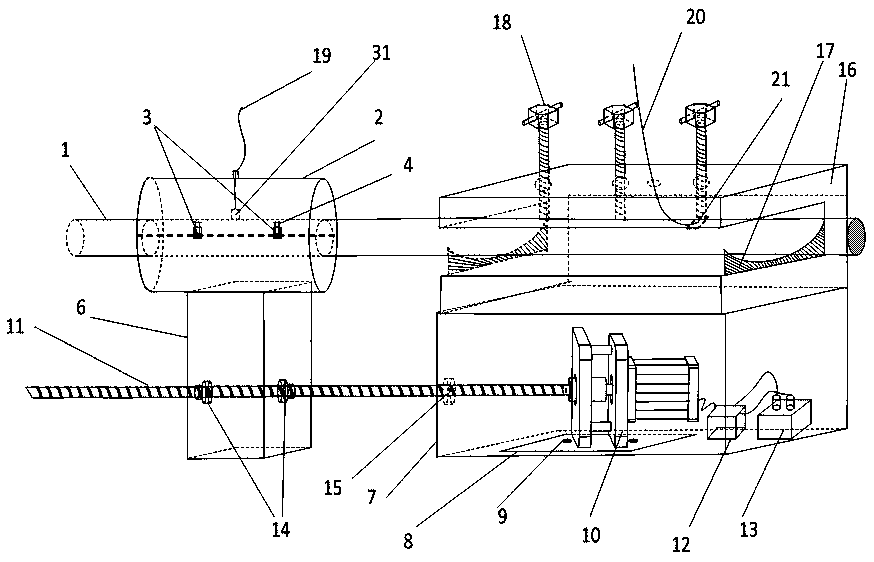
[0021] see figure 1 , The automatic derusting device for high-voltage bus joints in the field of the present invention mainly includes: a grinding device 2, an MCU controller 12, a stepping motor 10, a screw 11, a nut pair 14, a slider 6 and an impedance detection module. Wherein, the end of the high-voltage bus joint 1 that needs to be polished passes through the middle of the grinding device 2 horizontally. Grinding device 2 is fixedly connected with slide block 6, and slide block 6 is fixedly connected with nut pair 14, and nut pair 14 cooperates with screw mandrel 11, and stepping motor 10 is arranged horizontally, and its output shaft is fixedly connected with one end of screw mandrel 11, and screw mandrel 11 is connected with screw mandrel 11. The high-voltage bus connector 1 is parallel. Like this, stepper motor 10 works, and by driving screw mandrel 11 to rotate, thereby drives slide block 6 to move back and forth, makes grinding device 2 move back and forth along hig...
PUM
 Abstract
Description
Claims
Application Information
 - R&D
- Intellectual Property
- Life Sciences
- Materials
- Tech Scout
- Unparalleled Data Quality
- Higher Quality Content
- 60% Fewer Hallucinations
Browse by: Latest US Patents, China's latest patents, Technical Efficacy Thesaurus, Application Domain, Technology Topic, Popular Technical Reports.
© 2025 PatSnap. All rights reserved.Legal|Privacy policy|Modern Slavery Act Transparency Statement|Sitemap|About US| Contact US: help@patsnap.com