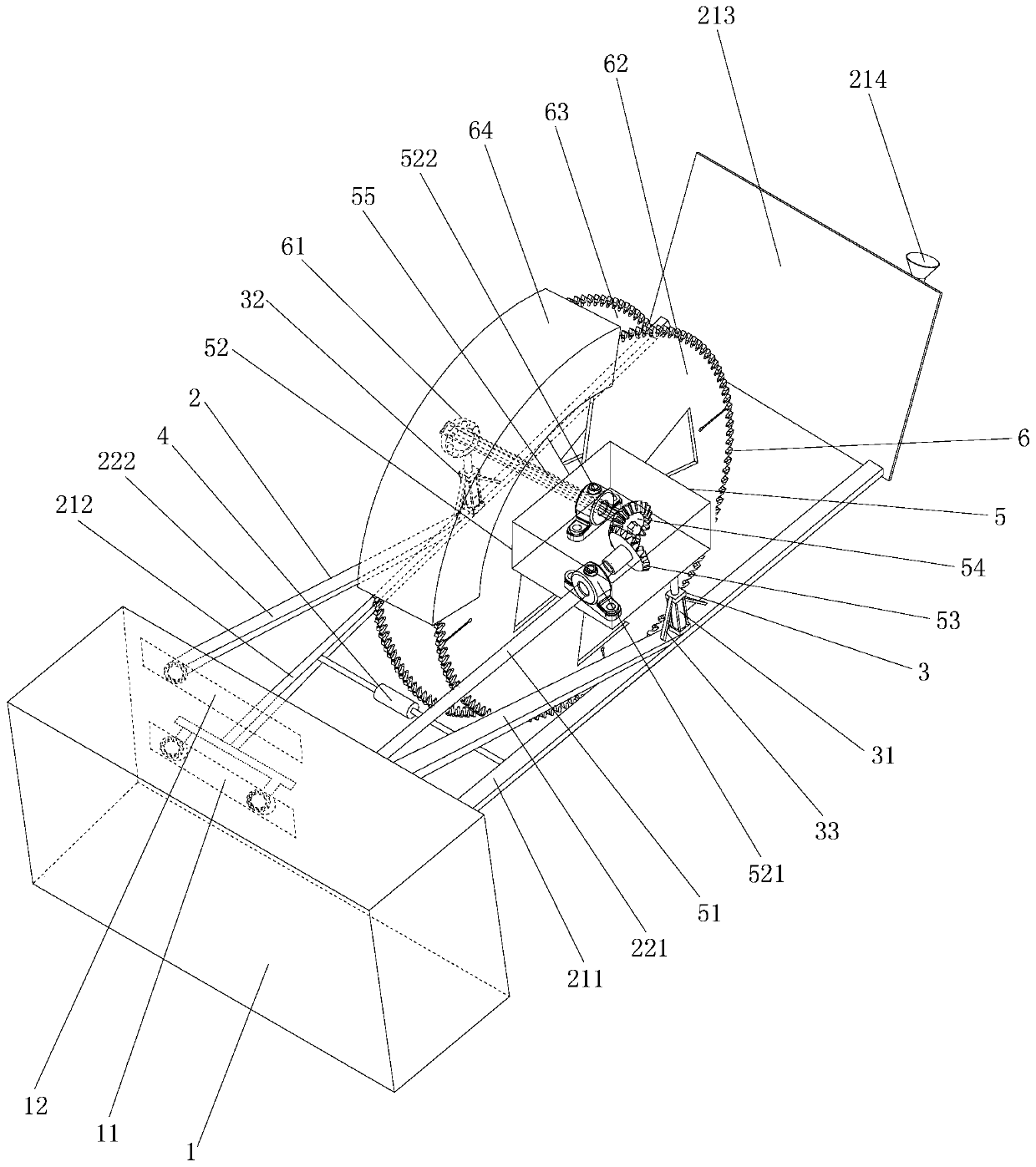
[0032] Such as figure 1 As shown, the rodent control isolation trenching and burying net device of the present invention includes a traction device 1, a fixing frame 2, a height adjustment hydraulic device 3, a width adjustment hydraulic device 4, a transmission mechanism 5 and a slice assembly 6.
[0033] The traction equipment 1 adopts a tractor, which is provided with a slicing drive device and a hydraulic system; wherein the front or rear of the traction equipment 1 is provided with a support frame slide 11 and a fixed pull rod slide 12 along a horizontal direction; the fixed pull rod slides The groove 12 is located on the upper side of the sliding groove 11 of the support frame.
[0034] The fixing frame 2 is installed on one side of the traction device 1, one side of which is a movable bracket movably connected to the traction device 1, and the opposite side is a fixed bracket fixedly connected to the traction device 1. The fixed frame 2 includes a supporting frame 21 and a fixed pull rod 22.
[0035] The support frame 21 includes a first support rod 211 and a second support rod 212 arranged in parallel left and right. One end of the first support rod 211 is fixedly connected to the front or rear side of the traction device 1, and the other end is fixedly connected to a mud guide 213; the front side of the mud guide 213 is fixedly provided with a water pipe guide tube 214. One end of the second support rod 212 is slidingly connected to the chute 11 of the support frame at the front or rear of the traction device 1 and locked and fixed by fasteners. The other end of the second support rod 212 is connected to the mud guide 213 Sliding contact on the back of the water pipe; the water pipe guide 214 is used to dig pipes while laying water pipes and cables; the mud guide 213 is used to collect the excavated soil to one side. The support frame 21 is not movable up and down, provides support for the slicing assembly 6 to be fixed, and the support for the slicing assembly 6 can be adjusted left and right as needed.
[0036] The fixed pull rod 22 is connected between the support frame 21 and the front or rear of the traction device 1, and includes a first fixed pull rod 221 and a second fixed pull rod 222 arranged in parallel left and right. The first fixed pull rod 221 and the first support rod 211 are located on the same side; one end of the first fixed pull rod 221 is fixedly connected to the front or rear of the traction device 1, and the other end is fixedly connected to the upper middle section of the first support rod 211. The second fixed pull rod 222 and the second support rod 212 are located on the same side; one end of the second fixed pull rod 222 is slidably connected to the fixed pull rod chute 12 at the front or rear of the traction device 1 and locked by fasteners The other end of the second fixed pull rod 222 is fixedly connected to the upper middle section of the second support rod 212.
[0037] The first support rod 211 and the first fixed pull rod 221 form a fixed support, and the second support rod 212 and the second fixed pull rod 222 form a movable support.
[0038] The height-adjusting hydraulic device 3 has a pair and is respectively matched with the connection between the fixed pull rods 22 and the support frame 21 that are vertically and fixedly installed on the left and right sides of the fixed frame 2. The hydraulic system on the traction equipment 1 is matched and connected; each height adjustment hydraulic device 3 is provided with a pair of hydraulic fixing rods 33 symmetrically inclined on opposite sides of the middle part. The upper end of the hydraulic fixing rod 33 is fixedly connected to the middle part of the height adjustment hydraulic device 3, and the lower end is with The fixing frame 2 is connected and fixed; the hydraulic fixing rod 33 can prevent the height adjustment hydraulic device 3 from shaking left and right, resulting in insufficient power. Wherein, the height adjustment hydraulic device 3 includes a first height adjustment hydraulic device 31 and a second height adjustment hydraulic device 32; the first height adjustment hydraulic device 31 and the second height adjustment hydraulic device 32 are connected to the traction equipment through a hydraulic pipeline. 1 is connected to the hydraulic system; the first height adjustment hydraulic device 31 is vertically fixedly installed at the connection between the first fixed pull rod 221 of the fixed pull rod 22 and the first support rod 211 of the support frame 21; the second height adjustment The hydraulic device 32 is vertically and fixedly installed at the connection between the second fixed pull rod 222 of the fixed pull rod 22 and the second support rod 212 of the support frame 21. At the same time, the height-adjusting hydraulic device 3, namely the first height-adjusting hydraulic device 31 and the second height-adjusting hydraulic device 32, is equipped with a height-adjusting hydraulic device protection shell.
[0039] The width adjustment hydraulic device 4 is a bidirectional output hydraulic device and is connected between the middle and rear sections of the support frame 21 of the fixed frame 2; the width adjustment hydraulic device 4 is also matched with the hydraulic system provided on the traction equipment 1 through a hydraulic pipeline connection. Among them, one of the power output ends of the width adjustment hydraulic 4 is fixedly connected to the middle and rear section of the first support rod 211 of the support frame 21 of the fixing frame 2, and the other power output end is fixedly connected to the second part of the support frame 21 of the fixing frame 2. The middle and rear section of the two support rods 212.
[0040] The transmission mechanism 5 is installed on the fixed frame 2 and includes a power transmission shaft 51, a gear fixing box 52, a first bevel gear 53, a second bevel gear 54 and a slice transmission shaft 55.
[0041] One end of the power transmission shaft 51 is connected to the power output end of the slicing drive device on the traction device 1, and the other end extends into the gear fixing box 52.
[0042] The gear fixing box 52 is fixed to the power output end of the height adjustment hydraulic device 3 on the other side of the fixing frame 2 specifically to the power output end of the first height adjustment hydraulic device 31 of the height adjustment hydraulic device 3. Wherein, a pair of gear transmission bearing housings, namely, a first gear transmission bearing housing 521 and a second gear transmission bearing housing 522 are fixedly arranged on the inner side of the gear fixing box 52.
[0043] The first bevel gear 53 and the second bevel gear 54 are matched and installed inside the gear fixing box 52; wherein, one end of the power transmission shaft 51 extending into the gear fixing box 52 passes through the first gear transmission bearing in the gear fixing box 52 The seat 521 is connected to the axial center of the first bevel gear 53.
[0044] The slicing transmission shaft 55 is a cross-shaped shaft structure, one end of which is connected to the slicing assembly 6, and the other end extends into the inner side of the gear fixing box 52 to connect to the second gear transmission bearing seat 522 and to the outside of the second gear transmission bearing seat 522 The second bevel gear 54 is installed on the end of the slice transmission shaft 55 that extends outside the second gear transmission bearing seat 522, and one side thereof is matched and meshed with the first bevel gear 53.
[0045] The slice assembly 6 includes a slice fixing assembly 61, a fixed slice 62, a movable slice 63 and a slice housing 64. The fixed slice 62 and the movable slice 63 are mounted on the slice transmission shaft 55 located between the gear fixing box 52 of the transmission mechanism 5 and the slice fixing assembly 61. The fixed slice 62 is close to the side of the gear fixing box 52 and is fixedly installed or welded on the slice transmission shaft 55 of the transmission mechanism 5. The movable slice 63 is matched and mounted on the slice transmission shaft 55 through the slice fixing assembly 61 and is axially slidably connected with the slice transmission shaft 55, and a cross-shaped hole matching the slice transmission shaft 55 is penetrated in the middle part. The fixed slice 62 has a disk-shaped structure, with movable slicing saw teeth arranged on its outer circumference, and movable slicing gaps on the disk surface. The movable slice 63 also has a disc-shaped structure, fixed slice saw teeth are arranged on the outer circumference, and movable slice gaps are arranged on the disk surface. The slice shell 64 is matched and covers the fixed slice 62 and the movable slice 63.
[0046] Such as figure 2 with image 3 As shown, the slice fixing assembly 61 is fixed to the power output end of the second height adjustment hydraulic device 32 of the height adjustment hydraulic device 3, and includes a fixing screw 611, a slice bearing 612, a bearing fixing buckle 613 and a bearing fixing ring 614. Wherein, the slice bearing 612 is fixed at the center of the movable slice 63 and one end extends to the outside of the movable slice 63. The bearing fixing buckle 613 is clamped on the inner side of the center of the slicing bearing 612 through the clamping teeth, and a cross-shaped hole matching the slicing transmission shaft 55 is opened in the middle; the slicing transmission shaft 55 passes through the movable slice 63 and the middle of the bearing fixing buckle 613 Cross-shaped hole. The bearing fixing buckle 613 is fixed to the movable slice 63 by a fixing screw 611. The bearing fixing ring 614 is open on one side and extending outward on both sides of the opening to form a pair of connecting arms 6141. The ends of the pair of connecting arms 6141 are provided with assembly holes 6142; the bearing fixing ring 614 is matched and sleeved on the slice bearing 612 The end of the movable slice 63 extending from the outside is locked and fixed by a pair of mounting holes 6142 on the connecting arm 6141 with a fastener 6143; the power output end of the second height adjusting hydraulic 32 of the height adjusting hydraulic 3 is fixed to the bearing The outer ring wall of the ring 614 is fixed.
[0047] In this embodiment, the length of the support frame 21 is 200 cm, the width adjustment hydraulic device 4 can be extended to a maximum of 60 cm, the height adjustment hydraulic device 3 can be extended to a maximum of 80 cm, and the movable slice 63 has a diameter of 200 cm. The length of the slicing drive shaft 55 is 100 cm, and the length of the water pipe guide tube 211 is 100 cm.
[0048] The structure of the invention is simple and reasonable in structure design, convenient to operate and use, high working efficiency, saving manpower and material resources, wide application range, effective prevention and control of rodent infestation, and effective protection of the ecological environment.