Heat insulation skeleton, heat insulation framework, heat insulation wall and construction method

A technology for thermal insulation of walls and skeletons, applied to walls, building materials, building components, etc., can solve problems such as fire prevention, poor durability, lack of heat storage function, and low service life, and achieve short construction periods, water saving and Artificial, monolithic light weight effect

Pending Publication Date: 2019-07-12
内蒙古科莱节能科技有限公司
View PDF0 Cites 0 Cited by
  • Summary
  • Abstract
  • Description
  • Claims
  • Application Information

AI Technical Summary

Problems solved by technology

[0003] 1. Thermal insulation technology attached to the outside of the building wall: Since there is only a 3-6mm protective layer on the outside of the thermal insulation layer, it is easy to crack, fall off, and has poor fireproof performance. Buildings need to be replaced many times during their life cycle, causing serious social problems
[0004] 2. Sandwich insulation building walls: suitable for cast-in-place concrete walls. Although the insulation layer is built into the concrete walls, it has many cold bridges, complicated construction and high cost
[0005] 3. Existing modular technology wall: its fire prevention and durability are poor, and it does not have heat storage function

Method used


Image

  • Heat insulation skeleton, heat insulation framework, heat insulation wall and construction method
  • Heat insulation skeleton, heat insulation framework, heat insulation wall and construction method
  • Heat insulation skeleton, heat insulation framework, heat insulation wall and construction method

Examples


Embodiment Construction

[0078] The present invention will be described below according to the embodiments shown in the accompanying drawings. It can be thought that embodiment disclosed this time is an illustration in every point, and is not restrictive. The scope of the present invention is not limited by the description of the following embodiments but only by the scope of the claims, and includes the same meaning as the scope of the claims and all modifications within the scope of the claims.

[0079] The following describes the thermal insulation framework and the thermal insulation wall involved in the present invention in detail in conjunction with the accompanying drawings.

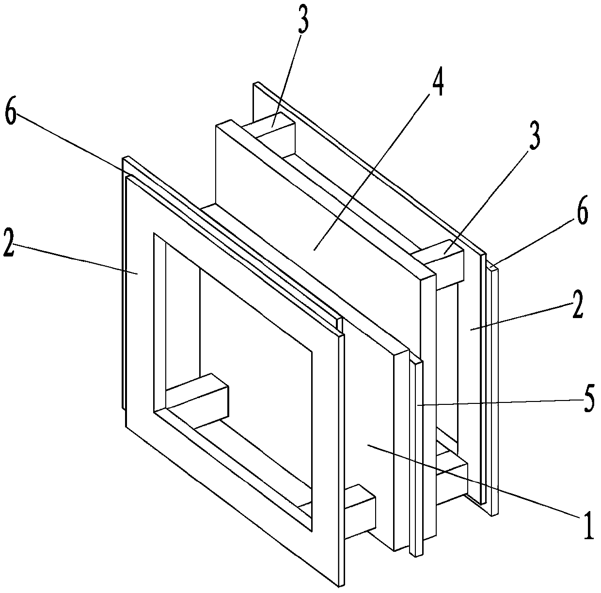
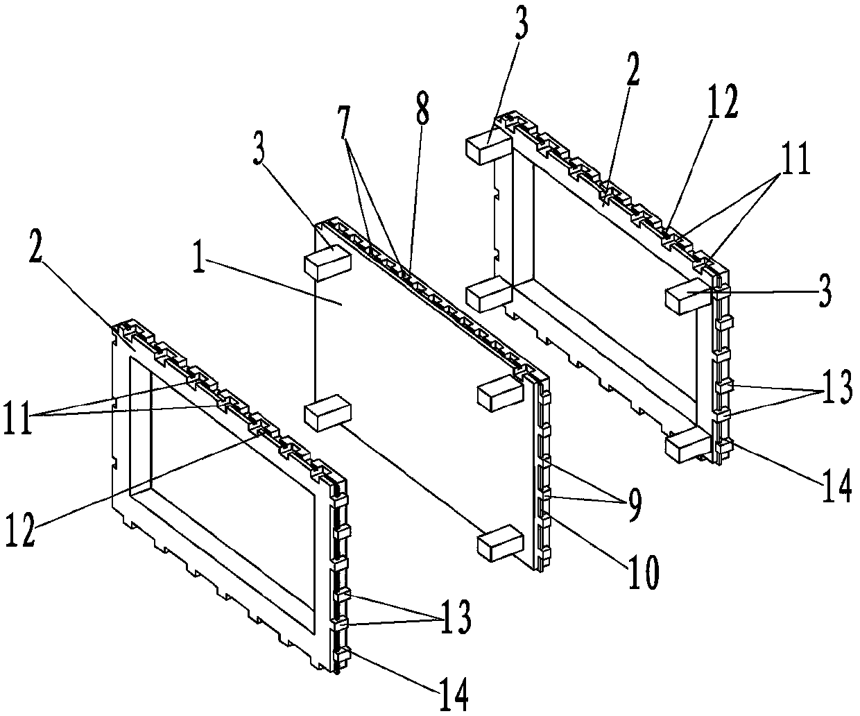
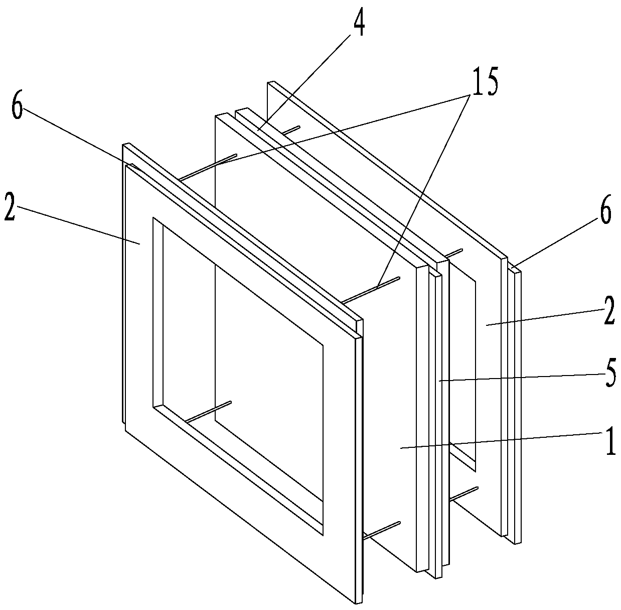
[0080] Such as figure 1 The structure diagram of Embodiment 1 of the thermal insulation framework of the present invention is shown, including a thermal insulation board 1 made of thermal insulation material, and one or both sides of the thermal insulation board 1 pass through at least one connecting block or at least on...


PUM


Abstract

The invention discloses a heat insulation skeleton, a heat insulation framework, a heat insulation wall and a construction method. The heat insulation skeleton comprises a heat insulation board; one face or two faces of the heat insulation board are connected with a frame through one or more connecting blocks, or one or more connecting blocks and connecting plates, or pulling connecting pieces; the heat insulation framework comprises the heat insulation skeleton, and the outer surfaces of one or more frames of the heat insulation skeleton are provided with surface layers; and the heat insulation wall comprises the one or more heat insulation frameworks, the multiple heat insulation frameworks are connected to form a heat insulation wall framework, and a cavity of the heat insulation wall framework is filled with foam cement or cement perlite or rubber powder particles or provided with steel bars and filled with concrete. Wall construction comprises the steps: construction paying off isconducted; the heat insulation frameworks are machined; the heat insulation frameworks are built and mounted to form the heat insulation wall framework; the heat insulation wall framework is supported; the steel bars are mounted in the inner cavity of the heat insulation wall framework; and the concrete is poured. The structure is simple, construction is convenient, the construction period is short, factory production can be conducted, the construction cost is low, construction water is saved, the service life is long, the wall has a heat storage function, the integrality is good, and the anti-seismic property is high.

Description

technical field [0001] The invention relates to the technical field of construction engineering, in particular to a thermal insulation frame, a thermal insulation frame, a thermal insulation wall and a construction method. Background technique [0002] In recent years, with the in-depth development of building wall innovation and building energy saving, the requirements for building wall energy saving and construction technology are getting higher and higher. The traditional wall energy saving technology has the following forms and existing technical defects: [0003] 1. Thermal insulation technology attached to the outside of the building wall: Since there is only a 3-6mm protective layer on the outside of the thermal insulation layer, it is easy to crack, fall off, and has poor fireproof performance. Buildings need to be replaced many times during their service life, causing serious social problems. [0004] 2. Sandwich insulation building walls: suitable for cast-in-plac...

Claims


Application Information

Patent Timeline
Patent Type & Authority Applications(China)
IPC IPC(8): E04C1/40E04B2/86
CPCE04B2/86E04B2/8629E04C1/40
Inventor 李天昊
Owner 内蒙古科莱节能科技有限公司
Why Eureka
Try Eureka