Shiplap seal arrangement

A technology of seals and vanes, applied in the field of overlapping devices, can solve the problems of large influence, wear of sealing devices, impossible accurate matching of shields, etc.

Active Publication Date: 2019-07-12
ANSALDO ENERGIA SWITZERLAND AG
View PDF6 Cites 0 Cited by
  • Summary
  • Abstract
  • Description
  • Claims
  • Application Information

AI Technical Summary

Problems solved by technology

However, if it is desired that adjoining components may have some "gap" (such as between two rotor blades in the rotor of a gas turbine, the "gap" is essential due to the fact that during operation the hot working medium resulting in the strong flow around the blade element), then the exact matching of two adjacent shrouds of the blade element...

Method used


Image

  • Shiplap seal arrangement
  • Shiplap seal arrangement
  • Shiplap seal arrangement

Examples


Embodiment Construction

[0024] With reference to the accompanying drawings, the technical content and detailed description of the present invention are described below according to preferred embodiments (not intended to limit the implementation scope of the present invention). Any equivalent changes and modifications made in accordance with the appended claims are covered by the presently claimed claims.

[0025] The present invention will now be described in detail with reference to the accompanying drawings.

[0026] refer to figure 1 , which is a schematic illustration of a flow diagram of an embodiment of a gas turbine for a power plant. figure 1 A gas turbine power plant 1 is disclosed which has an axis A and which successively along a main flow M comprises:

[0027] compressor section 2, which is provided with an inlet 11 for supply air 10,

[0028] A burner section with a burner 3 having a plurality of fuel nozzles 6 and a combustion chamber 4 in which compressed air is mixed with at leas...


PUM


Abstract

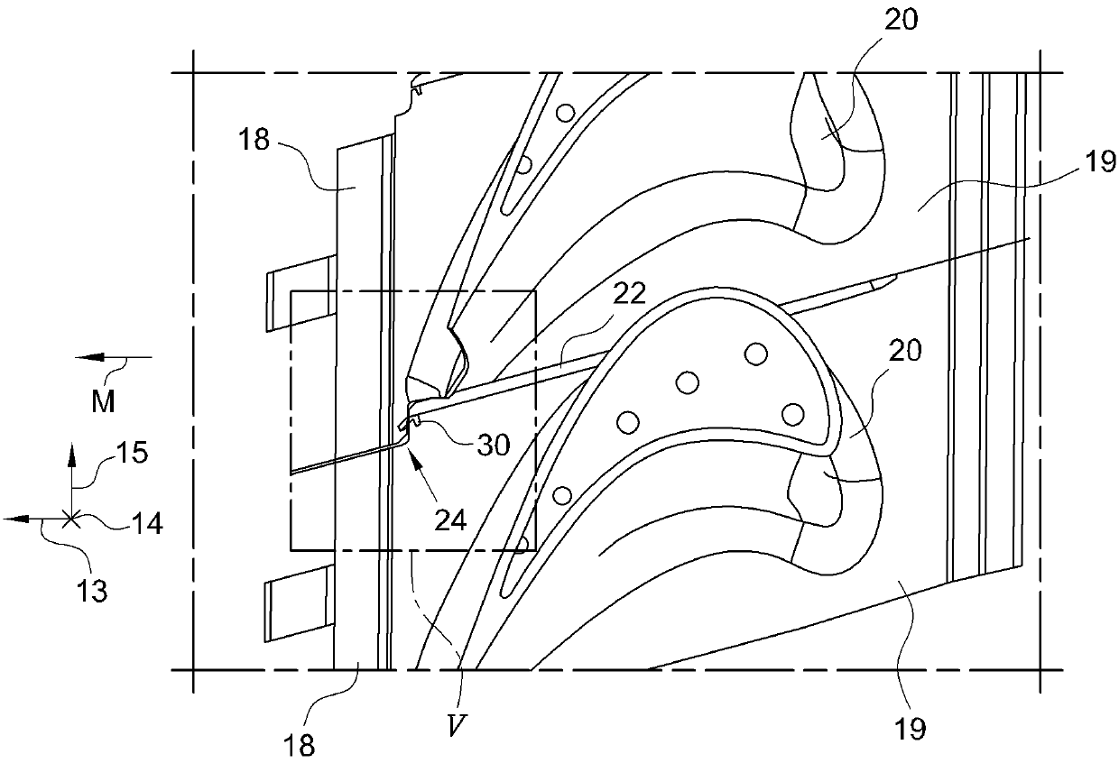
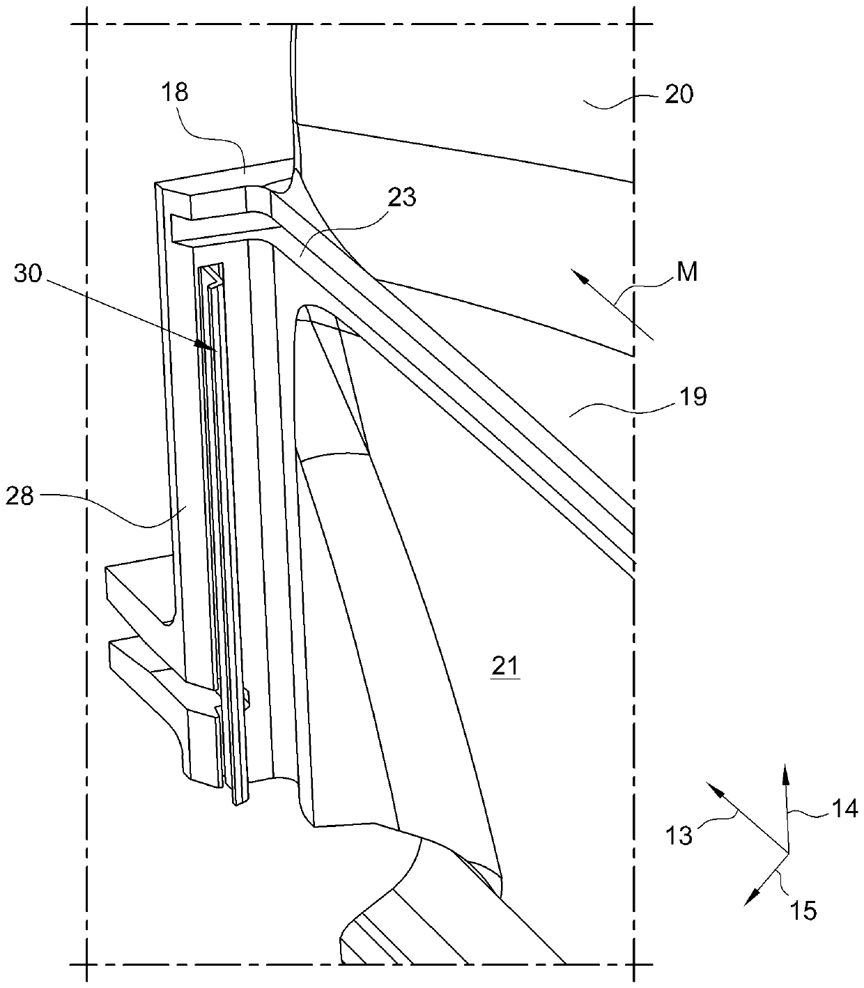
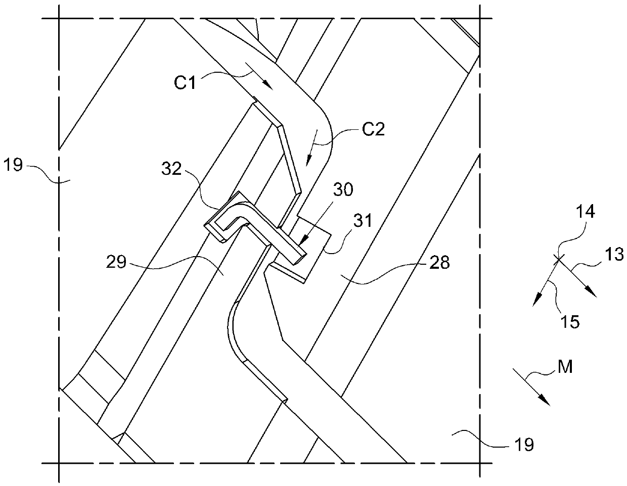
A shiplap arrangement for a gas turbine having an axis A; the shiplap arrangement comprising: a first and a second blade adjacent arranged along a circumferential direction centered in the gas turbineaxis A; each blade along a radial direction comprising a foot configured for coupling the blade to a rotor, a shank portion provided with a downstream closing wall, a platform and an airfoil; betweenthe adjacent blades in the shank portion a cooling air cavity is provided that is outwardly sealed by an axial seal arranged along the gap between the adjacent platforms and downstream sealed by a shiplap coupling between the adjacent shank closing walls; the shiplap coupling comprising a circumferential projecting portion of the shank closing wall of the first blade and a corresponding receivingrecess portion in the adjacent shank closing wall; a radial seal arranged along the gap between the projecting portion and the recess portion of the shiplap coupling and housed at one side in a firstradial groove realized in the projecting portion and at the other side in a second radial groove realized in the recess portion to provide a barrier against leakage flow passing through the shiplap coupling.

Description

[0001] Cross References to Related Applications [0002] This application claims priority from European Patent Application No. 17207850.3 filed on December 15, 2017, the disclosure of which is incorporated by reference. technical field [0003] The invention relates to a shiplap arrangement for a gas turbine. Background technique [0004] Conventional sealing means for sealing the space, such as rubber seals, polymer seals, adhesive means, or engagement of protrusions in grooves (as is encountered especially in the case of a seal between two static elements ), are generally known. In gas turbines, various components are cooled by means of cooling air flow in order to avoid thermal damage. This cooling air flow should be realized with the lowest possible losses in order to maximize the cooling potential. [0005] In order to achieve efficient sealing between two blade elements in a gas turbine, for example to prevent loss of cooling air due to leakage flows, it is necessa...

Claims


Application Information

Patent Timeline
IPC IPC(8): F01D11/00F01D5/18
CPCF01D11/008F01D5/18F01D11/006F05D2240/80
Inventor P.科瑟S.希文A.M.法利克-布鲁克斯
Owner ANSALDO ENERGIA SWITZERLAND AG
Why Eureka
Try Eureka