Interferometric optical fiber humidity sensor based on graphene and manufacturing method of interferometric optical fiber humidity sensor
A humidity sensor and graphene technology, which is applied in instruments, scientific instruments, and material analysis through optical means, can solve problems such as difficult observation, and achieve the effects of easy observation, high degree of reduction, and good film formation
- Summary
- Abstract
- Description
- Claims
- Application Information
AI Technical Summary
Problems solved by technology
Method used
Image
Examples
Embodiment 1
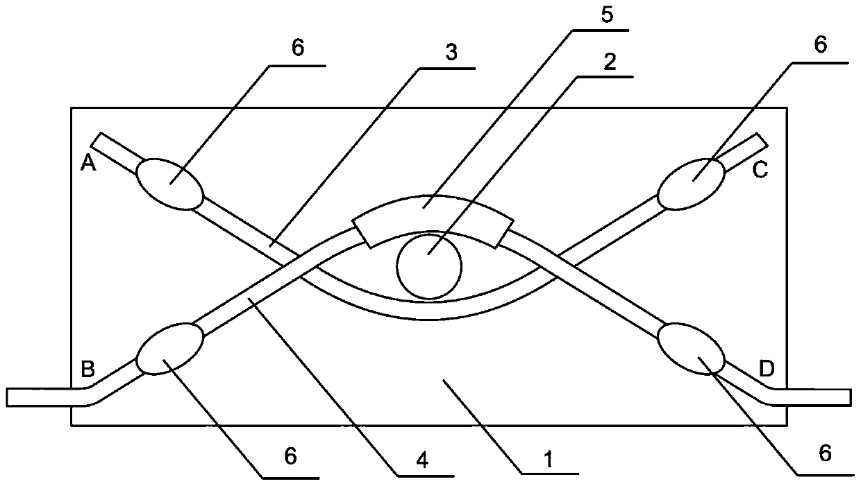
[0052] see figure 1 , one A graphene-based interferometric optical fiber humidity sensor, comprising: a glass slide 1 and two single-mode optical fibers (3, 4) bonded with a metal cylinder 2, and the two single-mode optical fibers pass through the two sides of the metal cylinder 2 respectively and face each other Bending to form two cross-coupling points, the two ends of the single-mode fiber are fixed on the glass slide 1, the middle part of the single-mode fiber is tapered, and the tapered waist region is located between the two cross-coupling points, one of the single-mode fiber The tapered waist area of the fiber is covered with the reduced graphene oxide film layer 5, and the two ends of the single-mode optical fiber covered with the reduced graphene oxide are respectively used as the input end and the output end. exist figure 1 Among them, the reduced graphene oxide is covered on the optical fiber 4, with the B end as the input end and the D end as the output end. ...
Embodiment 2
[0073] The sensor of this embodiment is exactly the same as the sensor of embodiment 1. The only difference is that the results of the humidity sensing experiment of different sensor samples of the same batch are as follows: Figure 6 and Figure 7 As shown, the position of the selected interference peak indicating the change of humidity is around 1570nm. The experimental temperature was 25°C and remained constant. In the range of 45%-95% relative humidity, the sensing sensitivity to rising humidity reaches 0.1934nm / %RH, and the sensing sensitivity to falling humidity reaches 0.2111nm / %RH. It has good recoverability.
Embodiment 3
[0075] The sensor of this embodiment is exactly the same as the sensor of embodiment 1. The only difference is that the results of the humidity sensing experiment of different sensor samples of the same batch are as follows: Figure 8 and Figure 9 As shown, the position of the selected interference peak indicating the change of humidity is around 1580nm. The experimental temperature was 25°C and remained constant. In the range of 45%-95% relative humidity, the sensing sensitivity to rising humidity reaches 0.1714nm / %RH, and the sensing sensitivity to falling humidity reaches 0.2226nm / %RH. It has good recoverability.
PUM
| Property | Measurement | Unit |
|---|---|---|
| diameter | aaaaa | aaaaa |
| diameter | aaaaa | aaaaa |
| height | aaaaa | aaaaa |
Abstract
Description
Claims
Application Information
 - R&D
- Intellectual Property
- Life Sciences
- Materials
- Tech Scout
- Unparalleled Data Quality
- Higher Quality Content
- 60% Fewer Hallucinations
Browse by: Latest US Patents, China's latest patents, Technical Efficacy Thesaurus, Application Domain, Technology Topic, Popular Technical Reports.
© 2025 PatSnap. All rights reserved.Legal|Privacy policy|Modern Slavery Act Transparency Statement|Sitemap|About US| Contact US: help@patsnap.com


