
Branch loaded three-band wave absorbing structure based on frequency selective surface

A frequency selective surface, three-band technology, applied in electrical components, antennas and other directions, can solve the problems of low selectivity, difficult to improve the quality factor Q of the equivalent circuit, etc., achieve good frequency selectivity, improve various characteristics, The effect of good angle stability

Inactive Publication Date: 2019-07-12
UNIV OF ELECTRONIC SCI & TECH OF CHINA
View PDF4 Cites 3 Cited by
  • Summary
  • Abstract
  • Description
  • Claims
  • Application Information

AI Technical Summary

Problems solved by technology

[0004] In view of the difficulty in improving the equivalent circuit quality factor Q of the miniaturized FSS unit in the prior art, resulting in the problem that the frequency selectivity of the miniaturized FSS unit is not high, the present invention provides a nodal loading based on a frequency selective surface The purpose of the three-band absorbing structure is to: optimize the patch-type frequency selective surface, so that the frequency selectivity of the absorbing structure is improved, and the angle stability of the frequency selective surface is improved, the absorbing performance is improved and the three-band absorbing is realized. function of

Method used


Image

  • Branch loaded three-band wave absorbing structure based on frequency selective surface
  • Branch loaded three-band wave absorbing structure based on frequency selective surface
  • Branch loaded three-band wave absorbing structure based on frequency selective surface

Examples


Embodiment Construction

[0022] All features disclosed in this specification, or steps in all methods or processes disclosed, may be combined in any manner, except for mutually exclusive features and / or steps.

[0023] Combine below Figure 1 to Figure 5 The present invention will be described in detail.

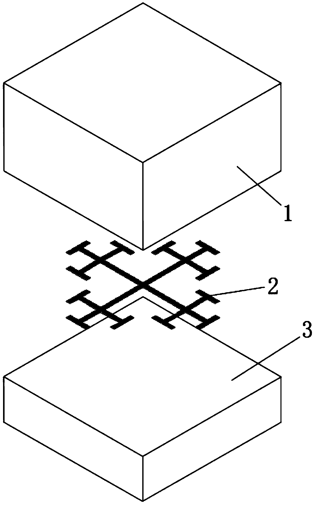
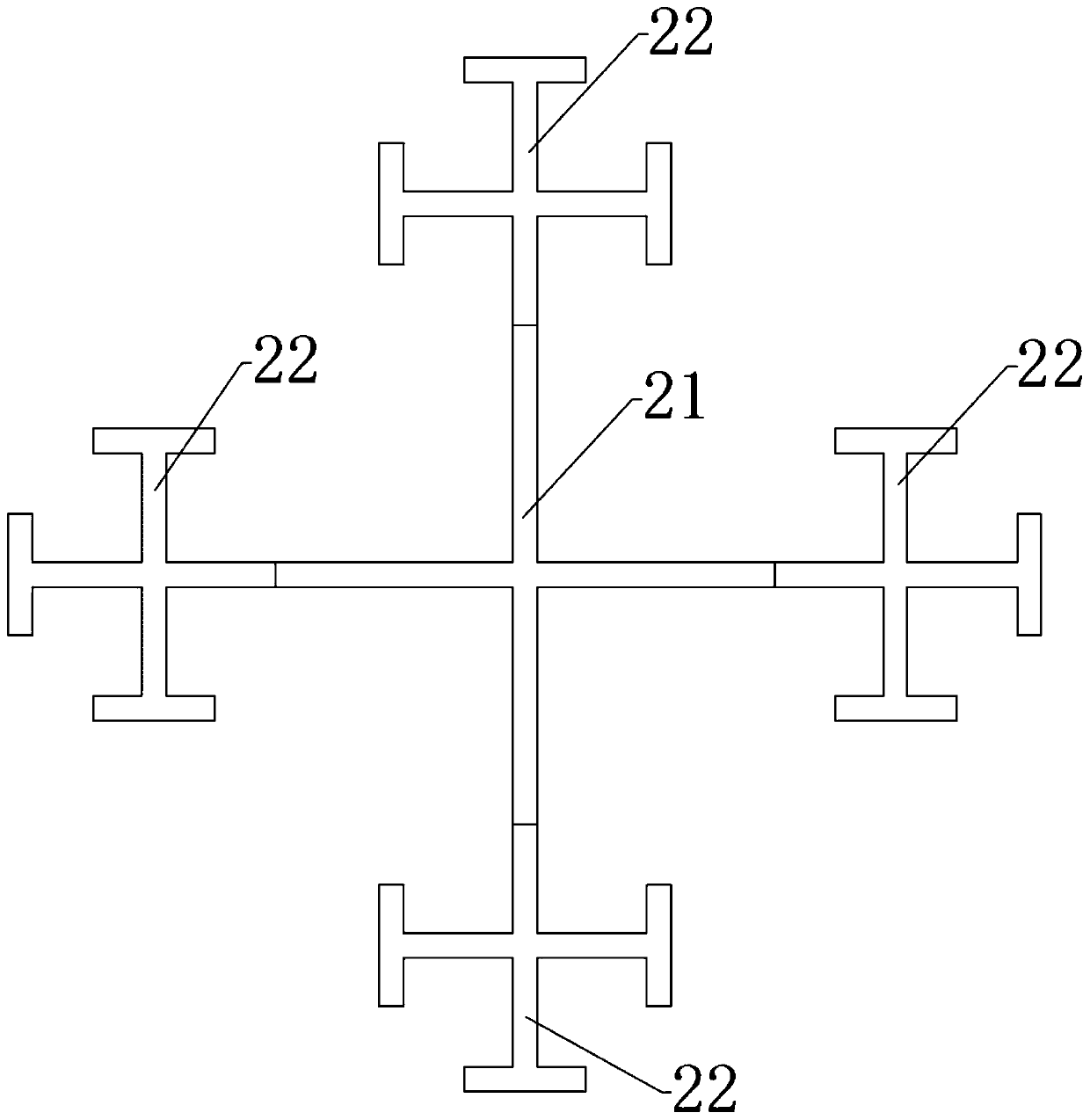
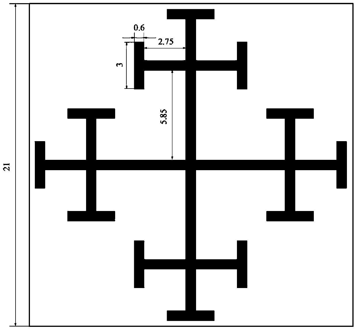
[0024] refer to figure 1 and figure 2 , a composite broadband absorbing structure based on a frequency selective surface, including an upper dielectric layer 1 , a frequency selective surface 2 and a lower dielectric layer 3 . The frequency selective surface 2 is printed on the upper surface of the lower dielectric layer 3 , or may also be printed on the lower surface of the upper dielectric layer 1 . The upper dielectric layer 1 and the lower dielectric layer 3 form a stacked structure. The frequency selective surface 2 is a passive resonant unit consisting of a cross-shaped structure 21 and four Jerusalem cross-shaped structures 22 respectively connected at the four ends of the cross-shaped s...


PUM

PropertyMeasurementUnit
Thicknessaaaaaaaaaa
Thicknessaaaaaaaaaa
Widthaaaaaaaaaa

Abstract

The invention discloses a frequency selective surface structure, which comprises an upper dielectric layer, a frequency selective surface and a lower dielectric layer. The frequency selective surfaceprovided by the invention is a composite structure of Jerusalem cross-shaped structures loaded with branches, a passive resonant unit of the frequency selective surface is composed of four Jerusalem cross-shaped structures and two mutually perpendicular branches, the Jerusalem cross-shaped structures are connected at four endpoints of the two mutually perpendicular branches, and the connection point is the endpoint of the cross-shaped frame with one arm rectangle being removed of the Jerusalem cross-shaped structure. The S11 parameter of structure reaches -15db within the wave absorbing rangeof 6-8GHZ, the structure has a great wave absorbing peak between 2.2-2.8GHZ and 11-12GHZ, has an excellent wave absorbing effect within three absorption bands of an incident wave angle below 45 degrees and possesses very good angle stability. The structure can be applied to various fields such as communication, environmental protection and human body protection.

Description

technical field [0001] The invention relates to the technical field of electromagnetic field and microwave communication, in particular to a tributary-loaded three-band wave-absorbing structure based on a frequency selective surface. Background technique [0002] In the traditional filter patch unit, when the plane wave is incident, the metal part is equivalent to an inductance, and the gap part is equivalent to a capacitor. Therefore, the whole unit can be equivalent to an LC series resonant circuit. When the frequency of the incident wave is high, the resistance of the inductor is large, and the transmission capacity of the two ports is relatively strong. When the frequency of the incident wave is low, the resistance of the capacitor is large, and the transmission capacity of the two ports is relatively high Strong, when the incident wave frequency reaches its resonant frequency, the LC series effect becomes the smallest impedance, and the transmission capability between t...

Claims


Application Information

Patent Timeline
IPC IPC(8): H01Q17/00H01Q15/00
CPCH01Q15/0013H01Q17/008
Inventor 韩旭丁帅
Owner UNIV OF ELECTRONIC SCI & TECH OF CHINA
Learn More