Composite magnetic coupling resonance type wireless power transmission coil
A resonant radio, transmission coil technology, applied in the direction of transformer/inductor coil/winding/connection, circuit, inductor, etc., can solve the problems of limiting the use range of magnetic coupling resonant wireless power transmission technology and occupying large equipment space. , to achieve the effect of good conductivity, increase loss, reduce mutual inductance and coupling coefficient
- Summary
- Abstract
- Description
- Claims
- Application Information
AI Technical Summary
Problems solved by technology
Method used
Image

Examples
Embodiment 1
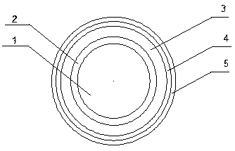
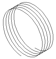
[0029] Embodiment 1, a composite magnetic coupling resonant wireless power transmission coil described in the present invention is a solenoid coil (such as image 3 ), the cross-section of the transmission line used for winding the coil is a multi-layered concentric circle, such as figure 1 As shown: it includes a solid copper conductor 1 , a first insulating layer 2 , a copper conductive layer 3 , a conductive layer 4 of high-conductivity material made of silver, and a second insulating layer 5 . The resonant frequency of the magnetically coupled resonant wireless power transfer (MCR-WPT) system designed in this embodiment is 1 MHz, and the thickness of the corresponding copper conductive layer 3 is 0.065 mm. The solid copper conductor 1 is a copper wire with a wire diameter of 1.8mm, the first insulating layer 2 is coated on the outer surface of the solid copper conductor 1, and the copper conductive layer 3 is plated on the On the outer surface of the first insulating laye...
Embodiment 2
[0030] Embodiment 2, a composite magnetic coupling resonant wireless power transmission coil described in the present invention is a planar spiral coil (such as Figure 4 ), the cross-section of the transmission line used for winding the coil is a multi-layered concentric circle, such as figure 1 As shown: it includes a solid copper conductor 1 , a first insulating layer 2 , a copper conductive layer 3 , a conductive layer 4 of high-conductivity material made of silver, and a second insulating layer 5 . The resonant frequency of the magnetically coupled resonant wireless power transfer (MCR-WPT) system designed in this embodiment is 1 MHz, and the thickness of the thin wall of the corresponding copper conductive layer is 0.065 mm. The solid copper conductor 1 is a copper wire with a wire diameter of 1.8mm, the first insulating layer 2 is coated on the outer surface of the solid copper conductor 1, and the copper conductive layer 3 is plated on the On the outer surface of the ...
Embodiment 3
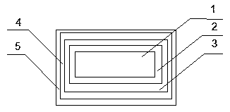
[0031] Embodiment 3, a composite magnetic coupling resonant wireless power transmission coil described in the present invention is a planar rectangular coil (such as Figure 5 ), the cross-section of the transmission line used for winding the coil is a multilayer concentric rectangle, such as figure 2 As shown: it includes a solid copper conductor 1 , a first insulating layer 2 , a copper conductive layer 3 , a conductive layer 4 of high-conductivity material made of silver, and a second insulating layer 5 . The resonant frequency of the magnetically coupled resonant wireless power transfer (MCR-WPT) system designed in this embodiment is 1 MHz, and the thickness of the corresponding copper conductive layer 3 is 0.065 mm. The solid copper conductor 1 is a copper conductor with a length of 1.8mm and a width of 0.8mm, the first insulating layer 2 is coated on the outer surface of the solid copper conductor 1, and the copper conductive layer 3 uses the NCVM non-conductive electro...
PUM
| Property | Measurement | Unit |
|---|---|---|
| thickness | aaaaa | aaaaa |
| radius | aaaaa | aaaaa |
| radius | aaaaa | aaaaa |
Abstract
Description
Claims
Application Information
 - R&D
- Intellectual Property
- Life Sciences
- Materials
- Tech Scout
- Unparalleled Data Quality
- Higher Quality Content
- 60% Fewer Hallucinations
Browse by: Latest US Patents, China's latest patents, Technical Efficacy Thesaurus, Application Domain, Technology Topic, Popular Technical Reports.
© 2025 PatSnap. All rights reserved.Legal|Privacy policy|Modern Slavery Act Transparency Statement|Sitemap|About US| Contact US: help@patsnap.com