Glass engraving and milling machine

A fine engraving machine and glass technology, applied in the field of CNC machine tools, can solve the problems of large space occupied by machine tools, sticking chips, splashing, etc., and achieve the effects of easy maintenance and operation, saving installation space and reducing space

Pending Publication Date: 2019-07-16
SHENZHEN CREATE CENTURY MACHINERY
View PDF0 Cites 4 Cited by
  • Summary
  • Abstract
  • Description
  • Claims
  • Application Information

AI Technical Summary

Problems solved by technology

[0002] In the previous glass engraving machines, the material frame for placing the workpiece to be processed was installed on the front side or on the left and right sides of the machine tool, resulting in a large footprint of the machine tool. When there is a problem with the main shaft or the workpiece, it is inconvenient for the operator to perform maintenance due to the influence of the front material frame, and because the material frame is relatively close to the main shaft, the cutting fluid will splash on the raw material glass of the material frame during processing, which will make the manipulator The phenomenon of sticking and sticking when grabbing the glass

Method used


Image

  • Glass engraving and milling machine
  • Glass engraving and milling machine
  • Glass engraving and milling machine

Examples


Embodiment Construction

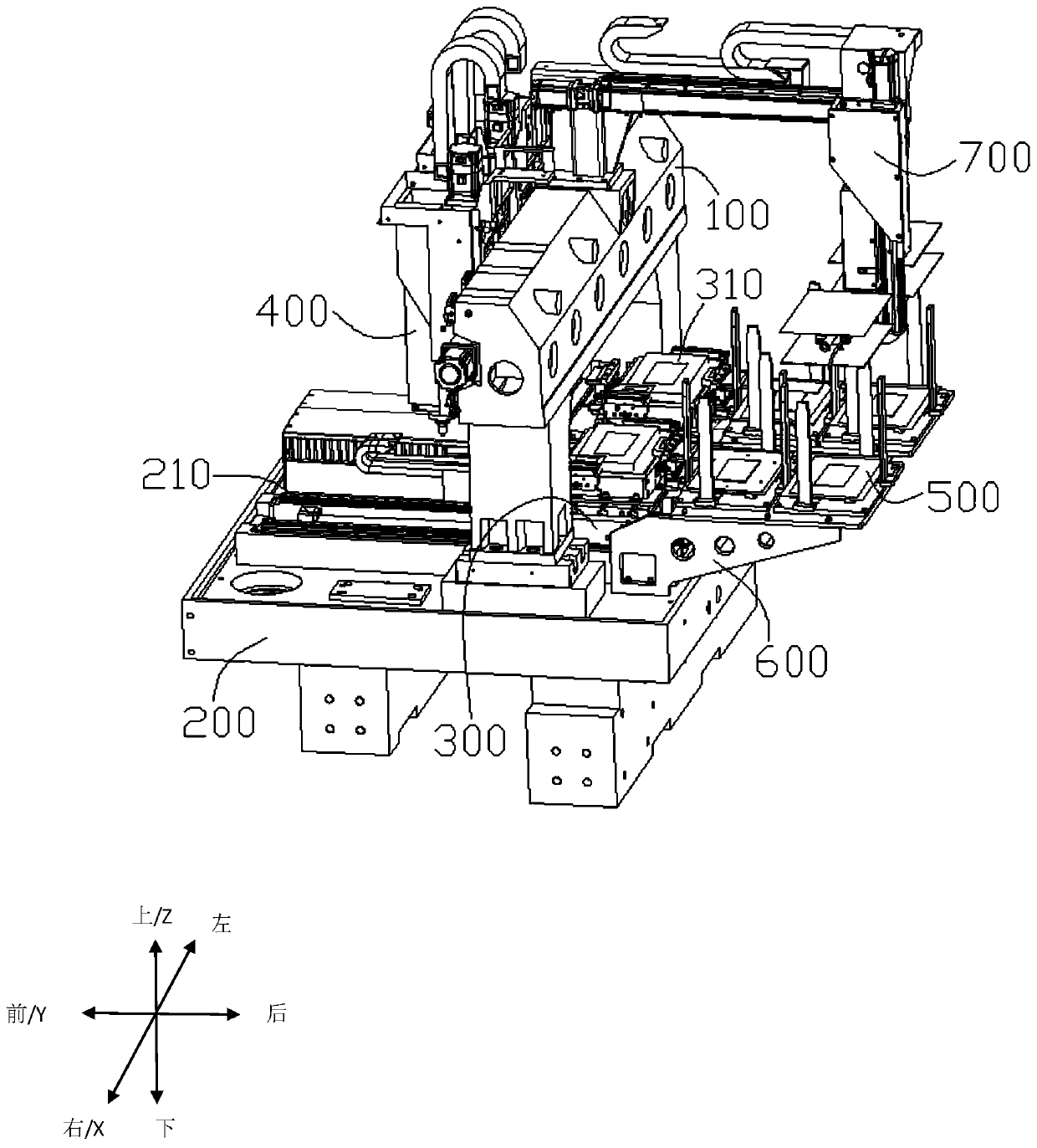
[0022] It should be noted that all directional indications (such as up, down, left, right, front, back...) in this embodiment are only used to explain the relative positions of the various components in a certain posture (as shown in the drawings) relationship, motion state, etc., if the specific gesture changes, the directional indication changes accordingly.

[0023] In addition, the descriptions involving "first", "second" and so on in the present invention are only for descriptive purposes, and should not be understood as indicating or implying their relative importance or implicitly indicating the quantity of the indicated technical features. Thus, the features defined as "first" and "second" may explicitly or implicitly include at least one of these features. In addition, the technical solutions of the various embodiments can be combined with each other, but it must be based on the realization of those skilled in the art. When the combination of technical solutions is co...


PUM


Abstract

The invention provides a glass engraving and milling machine. The glass engraving and milling machine comprises a gantry frame, a bed body, a workbench, a processing spindle, a material frame, and a mechanical hand, the gantry frame is arranged on the bed body, the processing spindle is located on the front face of the gantry frame, a Y-axis guiding rail on the bed body extends to the area corresponding to the back face of the gantry frame from the area corresponding to the front face of the gantry frame, the material frame is arranged at the back part of the bed body relative to the back faceof the gantry frame, the workbench is arranged above the Y-axis guiding rail, and the arraying directions of the workbench and the material frame are parallel to the Y-axis; and the mechanical hand is located on the back face of the gantry frame, the material changing between the workbench and the material frame is achieved, the material frame comprises a picking material frame and a storing material frame, and the arraying directions of the picking material frame and the storing material frame are parallel to the Y-axis. According to the glass engraving and milling machine, the material frame and the mechanical hand are placed in the rear of the gantry frame, so that the feeding and discharging areas are away from the processing area, the fact that the cutting fluid splashes the workpiece in the material frame in the machining process is avoided, and the adhesion of the two or multiple workpieces due to the water vapor is prevented.

Description

technical field [0001] The invention relates to the technical field of numerical control machine tools, in particular to glass processing equipment. Background technique [0002] In the previous glass engraving machines, the material frame for placing the workpiece to be processed was installed on the front side or on the left and right sides of the machine tool, resulting in a large footprint of the machine tool. When there is a problem with the main shaft or the workpiece, it is inconvenient for the operator to perform maintenance due to the influence of the front material frame, and because the material frame is relatively close to the main shaft, the cutting fluid will splash on the raw material glass of the material frame during processing, which will make the manipulator When grabbing the glass, the phenomenon of adhesion and sticking occurs. Contents of the invention [0003] The present invention provides a glass engraving machine in order to solve the above probl...

Claims


Application Information

Patent Timeline
Patent Type & Authority Applications(China)
IPC IPC(8): B44B3/00B44B3/06
CPCB44B3/00B44B3/06
Inventor 袁志刚何清江
Owner SHENZHEN CREATE CENTURY MACHINERY
Why Eureka
Try Eureka