
Wavefront correction method based on image moment characteristics

A wavefront correction and image feature technology, applied in the wavefront field, can solve problems such as high energy requirements, limited application range, and inability to meet requirements, and achieve high bandwidth, strong robustness, anti-noise ability, and simple mechanism Effect

Inactive Publication Date: 2019-07-16
INST OF OPTICS & ELECTRONICS - CHINESE ACAD OF SCI
View PDF3 Cites 2 Cited by
  • Summary
  • Abstract
  • Description
  • Claims
  • Application Information

AI Technical Summary

Problems solved by technology

[0003] The wavefront correction technology with wavefront detection uses the Hartmann detector to measure the wavefront of the received beam, and then drives the deformable mirror to correct the wavefront distortion. It has the advantages of high precision and high bandwidth, but the Hartmann detector does not The energy requirements are high, resulting in most of the received beam being split into the Hartmann detector, and the scope of application is limited
[0004] The wavefront correction technology without wavefront detection directly controls the deformable mirror, takes the fiber coupling efficiency as the objective function, and achieves the maximum fiber coupling efficiency through optimization algorithm iterations. The main disadvantage is that the bandwidth is insufficient and cannot meet the needs of practical applications.

Method used


Image

  • Wavefront correction method based on image moment characteristics
  • Wavefront correction method based on image moment characteristics
  • Wavefront correction method based on image moment characteristics

Examples


Embodiment Construction

[0029] The specific implementation manners of the present invention will be described in detail below in conjunction with the accompanying drawings.

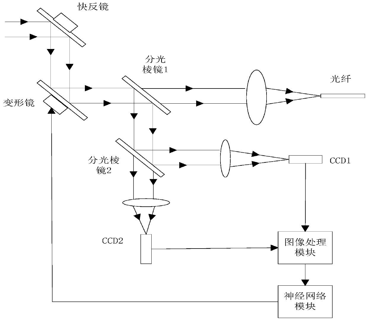
[0030] Such as figure 1 As shown, the wavefront correction method based on image moment features uses devices including: an image acquisition module, an image processing module, a neural network module and an actuator. The specific method is as follows: the incident light is divided into two by the beam splitter, and converged into a focused spot and a defocused spot respectively. The image acquisition module is responsible for collecting the spot; the image processing module is responsible for the image moment calculation of the spot, and the extracted image The feature is used as the input of the neural network; after a large number of image feature training, the neural network module fits the corresponding Zernike coefficient according to the image feature passed by the image processing module; finally, the actuator implement...


PUM


Abstract

The invention discloses a wavefront correction method based on image moment characteristics. The method uses a device, and the device comprises an image acquisition module, an image processing module,a neural network module and an execution mechanism. The specific method comprises the steps that incident light is divided into two light spots through a spectroscope, the incident light are converged into a focused light spot and a defocused light spot respectively, and an image collection module is responsible for collecting the light spots; the image processing module is responsible for carrying out image moment operation on the light spots and taking characteristics extracted after the image moment operation as the input of the neural network; after training of a large number of image features, the neural network module fits a corresponding Zernike coefficient according to the image features transmitted by the image processing module; and finally, the execution mechanism corrects thewavefront distortion generated by the atmospheric turbulence according to the fitted Zernike coefficient.

Description

technical field [0001] The invention relates to the field of wavefront technology, in particular to a wavefront correction method based on image moment features, which is mainly used for correcting wavefront distortion generated by atmospheric turbulence. Background technique [0002] Due to the influence of atmospheric turbulence in space optical communication, there is wavefront distortion in the receiving beam, which affects the coupling efficiency and stability of the optical fiber, and then affects the bit error rate of communication. At present, the main method for correcting wavefront distortion is wavefront correction technology, which includes wavefront correction technology with wavefront detection and wavefront correction technology without wavefront detection. [0003] The wavefront correction technology with wavefront detection uses the Hartmann detector to measure the wavefront of the received beam, and then drives the deformable mirror to correct the wavefront...

Claims


Application Information

Patent Timeline
Patent Type & Authority Applications(China)
IPC IPC(8): G06N3/04G06N3/08G02B26/06G06K9/62
CPCG06N3/04G06N3/08G02B26/06G06F18/214
Inventor 徐杨杰黄永梅王强贺东郭弘扬
Owner INST OF OPTICS & ELECTRONICS - CHINESE ACAD OF SCI
Learn More