Supercharge Your Innovation With Domain-Expert AI Agents!

Phase inductance non-saturation positioning-based position sensorless control method and device of switch reluctance machine

A technology of switched reluctance motors and control methods, which is applied in motor control, AC motor control, control systems, etc., and can solve problems such as heavy computing workload, increased data processing complexity and computing workload, and large occupation of system resources.

Active Publication Date: 2019-07-16
HUNAN UNIV OF SCI & TECH
View PDF5 Cites 3 Cited by
  • Summary
  • Abstract
  • Description
  • Claims
  • Application Information

AI Technical Summary

Problems solved by technology

Among them, the principle of the inductance model method is simple, but it takes up a lot of system resources, and the flexibility and real-time performance are not high; the position estimation accuracy of the intelligent control method is high, but the algorithm is complicated and the calculation workload is large; the flux linkage / current method overcomes the above two The disadvantage of the method is that it has the advantages of less system resource occupation and moderate computing workload, but it will produce a large estimation error when the magnetic circuit is saturated.
In view of the above-mentioned problems in the flux linkage / current method, the patent application CN 108712127 A submitted by the applicant on June 4, 2018 discloses a position sensorless control method and device for a switched reluctance motor. The method proposed by the method mainly It involves a rotor position correction method when the motor magnetic circuit is saturated. This method can effectively improve the estimation accuracy of the rotor position when the motor magnetic circuit is saturated, but it also increases the complexity of data processing and the workload of calculation.

Method used


Image

  • Phase inductance non-saturation positioning-based position sensorless control method and device of switch reluctance machine
  • Phase inductance non-saturation positioning-based position sensorless control method and device of switch reluctance machine
  • Phase inductance non-saturation positioning-based position sensorless control method and device of switch reluctance machine

Examples


Embodiment 1

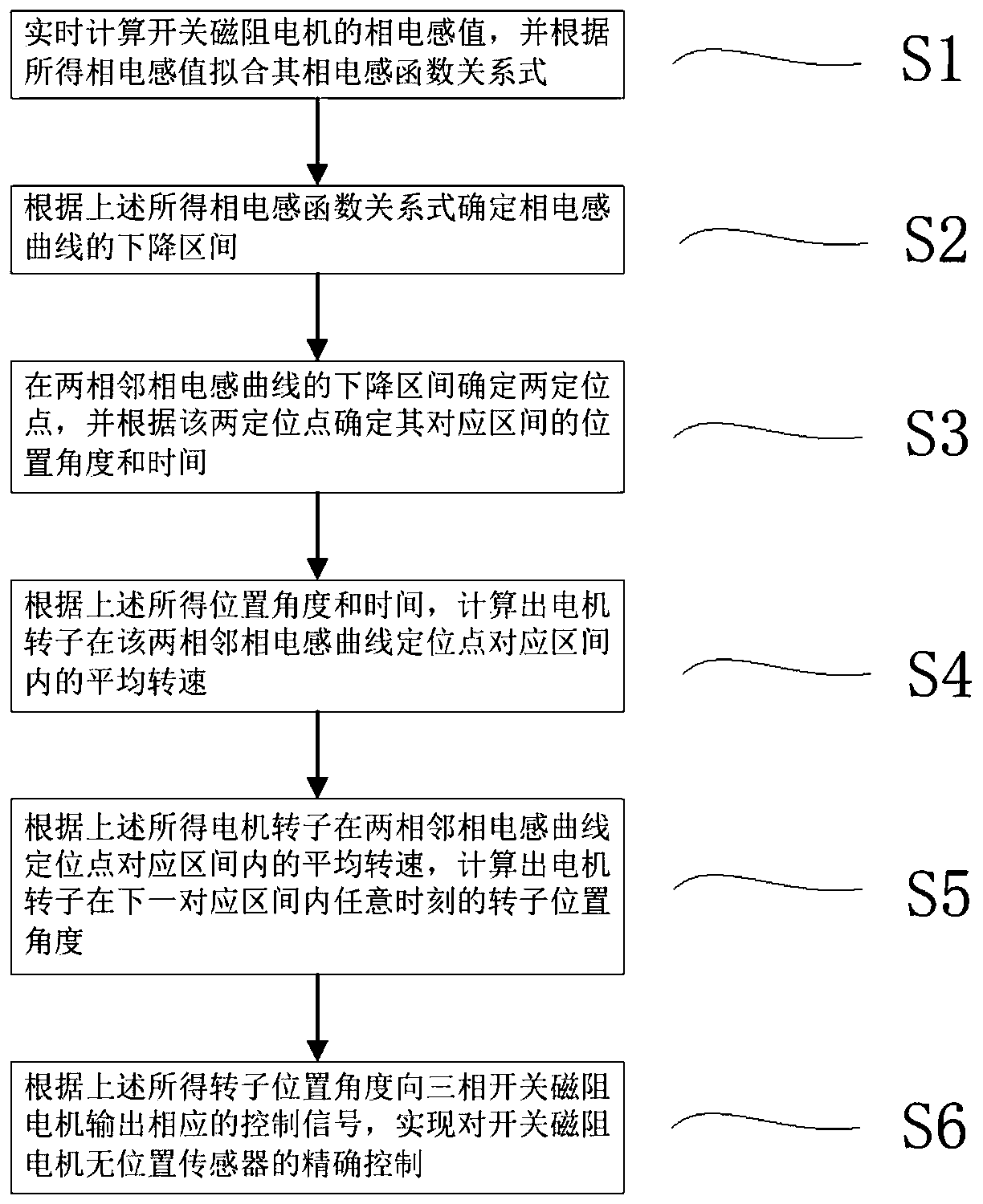
[0061] figure 1 The schematic flow chart of the control method provided by the present invention, the specific steps of the method are as follows:

[0062] Step S1)

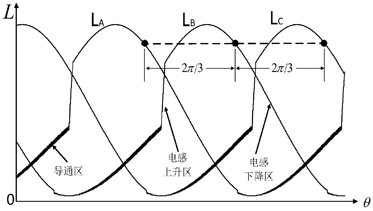
[0063] figure 2 It is the phase inductance curve diagram under the magnetic circuit saturation state of the switched reluctance motor of the present invention, as figure 2 As shown, for a three-phase switched reluctance motor, if the first conduction phase of the motor in the rotor cycle is phase A, the subsequent conduction phase is phase B, and the last conduction phase is phase C, so the formula (2 ) L k (θ) = B 0 +B 1 cos(θ-2π(k-1) / m)+B 2 cos2(θ-2π(k-1) / m) can get the three-phase phase inductance function expression as shown in formula (2-1) ~ formula (2-3):

[0064] L A (θ) = B 0 +B 1 cos(θ)+B 2 cos2(θ) (2-1)

[0065] L B (θ) = B 0 +B 1 cos(θ-2π / 3)+B 2 cos2(θ-2π / 3) (2-2)

[0066] L C (θ) = B 0 +B 1 cos(θ-4π / 3)+B 2 cos2(θ-4π / 3) (2-3)

[0067] In the formula: L A (θ), L B (θ), L C (θ)...

Embodiment 2

[0107] Figure 5 It is a structural block diagram of the position sensorless control device of the switched reluctance motor based on the positioning of the phase inductance unsaturated region of the present invention, and the control device includes a microcontroller, a pulse generation module, a power conversion circuit, a current detection module, a voltage detection module and a timer module, where:

[0108] The power conversion circuit such as Figure 6 As shown, it includes several phase power conversion units, each phase power conversion unit adopts an asymmetrical half-bridge structure, and each phase power conversion unit includes a first main power switch Q1, a second main power switch Q2, a first freewheeling diode D1 , the second freewheeling diode D2, the bus voltage input terminal J1 and J2, the bus voltage input terminal J1 and J2 are connected to the voltage detection module at the same time; the first main power switch Q1 and the first freewheeling diode D1 a...


PUM


Abstract

The invention discloses a phase inductance non-saturation positioning-based position sensorless control method and device of a switch reluctance machine. The control method comprises the steps of calculating an average rotational speed of a motor rotor within a corresponding zone of two positioning points by determining the positioning points at reduction zones of two adjacent phase inductance curves; and finally, calculating a rotor position angle of the motor rotor at an arbitrary moment within a next corresponding zone according to the average rotational speed. The control device comprisesa microcontroller, a pulse generation module, a power conversion circuit, a current detection module, a voltage detection module and a timer module. Compared with the prior art, the phase inductance non-saturation positioning-based position sensorless control method and device of the switch reluctance machine have the characteristics of algorithm simplicity, high position estimation accuracy and the like.

Description

technical field [0001] The invention relates to the field of switched reluctance motor control, in particular to a position sensorless control method and device for a switched reluctance motor based on the positioning of a phase inductance unsaturated region. Background technique [0002] Switched reluctance motors have a series of advantages such as small starting current, large starting torque, high efficiency, simple and solid structure, strong fault tolerance, and wide speed range, and have been widely used in many fields. In order to realize the high-performance control of the switched reluctance motor, it is necessary to obtain the position information of the motor rotor accurately. Traditional rotor position detection methods mainly use photoelectric, electromagnetic and other position sensors, but the introduction of position sensors not only increases the cost and complexity of the system, but also reduces the reliability and environmental adaptability of the system...

Claims


Application Information

Patent Timeline
Patent Type & Authority Applications(China)
IPC IPC(8): H02P6/18H02P25/089
CPCH02P6/18H02P25/089H02P2203/01
Inventor 张小平匡斯建刘苹张光辉张铸姜海鹏
Owner HUNAN UNIV OF SCI & TECH
Features
  • R&D
  • Intellectual Property
  • Life Sciences
  • Materials
  • Tech Scout
  • Unparalleled Data Quality
  • Higher Quality Content
  • 60% Fewer Hallucinations
Learn More