Aortic pump devices

A technology of aortic valve and ascending aorta, applied in circulatory assist device, blood pump, medical science, etc., can solve the problems of inability to provide blood flow output, size limitation, etc.

Active Publication Date: 2019-07-16
BERLIN HEART GMBH
View PDF8 Cites 1 Cited by
  • Summary
  • Abstract
  • Description
  • Claims
  • Application Information

AI Technical Summary

Problems solved by technology

[0006] Among other things, the inventors have recognized the problem to be solved that transluminal implantabl

Method used


Image

  • Aortic pump devices
  • Aortic pump devices
  • Aortic pump devices

Examples


Embodiment Construction

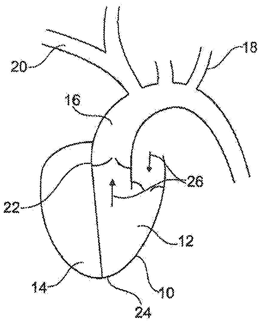
[0023] Figure 1a A simplified schematic diagram of a human heart 10 is shown. The human heart has a left ventricle 12 and a right ventricle 14 .

[0024] For the purposes herein, of particular interest are blood flow and vessels around the left ventricle. Arrow 26 shows blood flowing into the left ventricle and out through the aortic heart valve 22 and into the aorta 16 . Three branches are shown leaving the aorta in an upward direction. Of particular interest in this context are the subclavian arteries (left subclavian artery 18, right subclavian artery 20). The guidewire / lead shown here is primarily routed through the right subclavian artery 20 . It is desired to implant the pump in the region of the aortic valve 22 and is preferably inserted through the apex 24 of the heart.

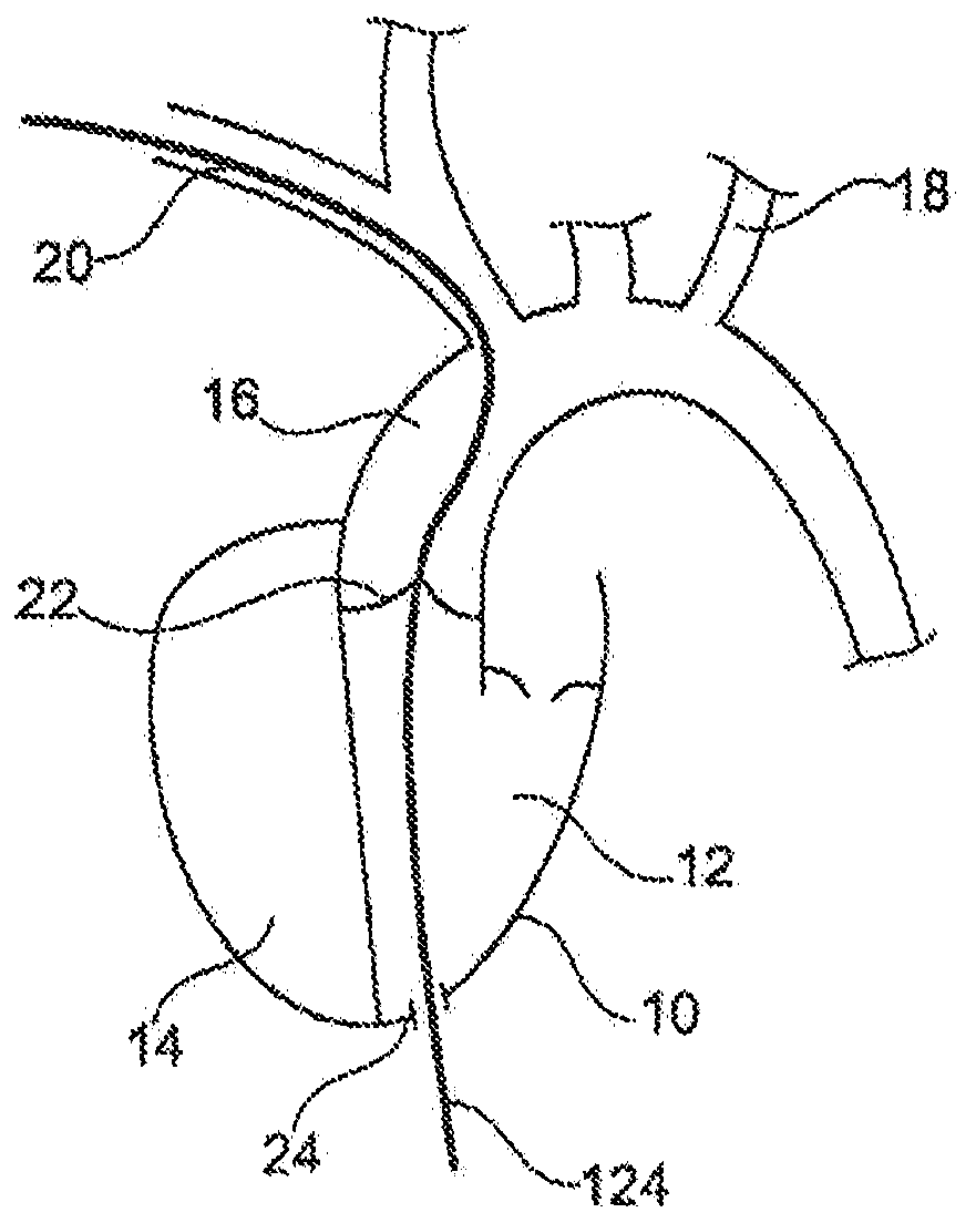
[0025] exist Figure 1b This example is shown in detail in . Using the so-called "Seldinger" technique, a guide wire 124 can be brought into the right subclavian artery. A guidewire is guided...


PUM


Abstract

A disclosed apparatus or method can include or use a non-transluminally implantantable blood pump housing, which can be sized and shaped to be implanted at an aortic valve of a human subject, the pumphousing can include: a pump housing cross-sectional profile size that is larger than is passable via a blood vessel of the human subject; and a power connection, configured for being electrically connected to an intravascular lead that is sized and shaped to extend from the pump housing through a subclavian artery of the human subject.

Description

technical field [0001] This document relates generally to implantable heart pumps and ventricular assist devices, and in particular but not limited to non-transluminal implantable blood pumps and power connectors connected thereto, and related methods of implantation and use. Background technique [0002] Ventricular assist devices include left ventricular (LV) pumps that can be used, for example, in patients awaiting heart transplantation, or in, for example, helping to treat heart failure in New York Heart Association (NYHA) Class III to IV patients In, it helps the heart pump blood to the circulatory system. [0003] For example, US Patent No. 8,684,905 B2 to Jeeyanandam et al. relates to devices and methods for implanting, positioning, removing, replacing, and operating an intra-aortic balloon pump. [0004] In another example, European Patent No. EF 1 789 112 B1 relates to a device for long-term assistance in pumping blood from the left ventricle. [0005] In yet anot...

Claims


Application Information

Patent Timeline
IPC IPC(8): A61M1/10A61M60/135A61M60/139A61M60/226A61M60/81A61M60/861A61M60/865A61M60/873A61M60/878
CPCA61M60/135A61M60/226A61M60/865A61M60/81A61M60/878A61M60/861A61M60/139A61M60/873
Inventor A·K·梅农P·努瑟尔
Owner BERLIN HEART GMBH
Why Eureka
Try Eureka