Ultrasonic fuel excitation device

A technology of excitation device and ultrasonic wave, applied in fuel injection device, low pressure fuel injection, low pressure fuel injection and other directions, can solve the problems of large heat loss of engine fuel and low thermal efficiency, and achieve the effect of enhancing equipment power, protecting the environment and saving fuel

Pending Publication Date: 2019-07-19
方荣武 +2
View PDF1 Cites 2 Cited by
  • Summary
  • Abstract
  • Description
  • Claims
  • Application Information

AI Technical Summary

Problems solved by technology

[0004] In order to solve the problems of large heat loss and low thermal efficiency of existing engine fuels, the present invention provides an ultrasonic fuel excitation device

Method used


Image

  • Ultrasonic fuel excitation device
  • Ultrasonic fuel excitation device
  • Ultrasonic fuel excitation device

Examples


Embodiment 1

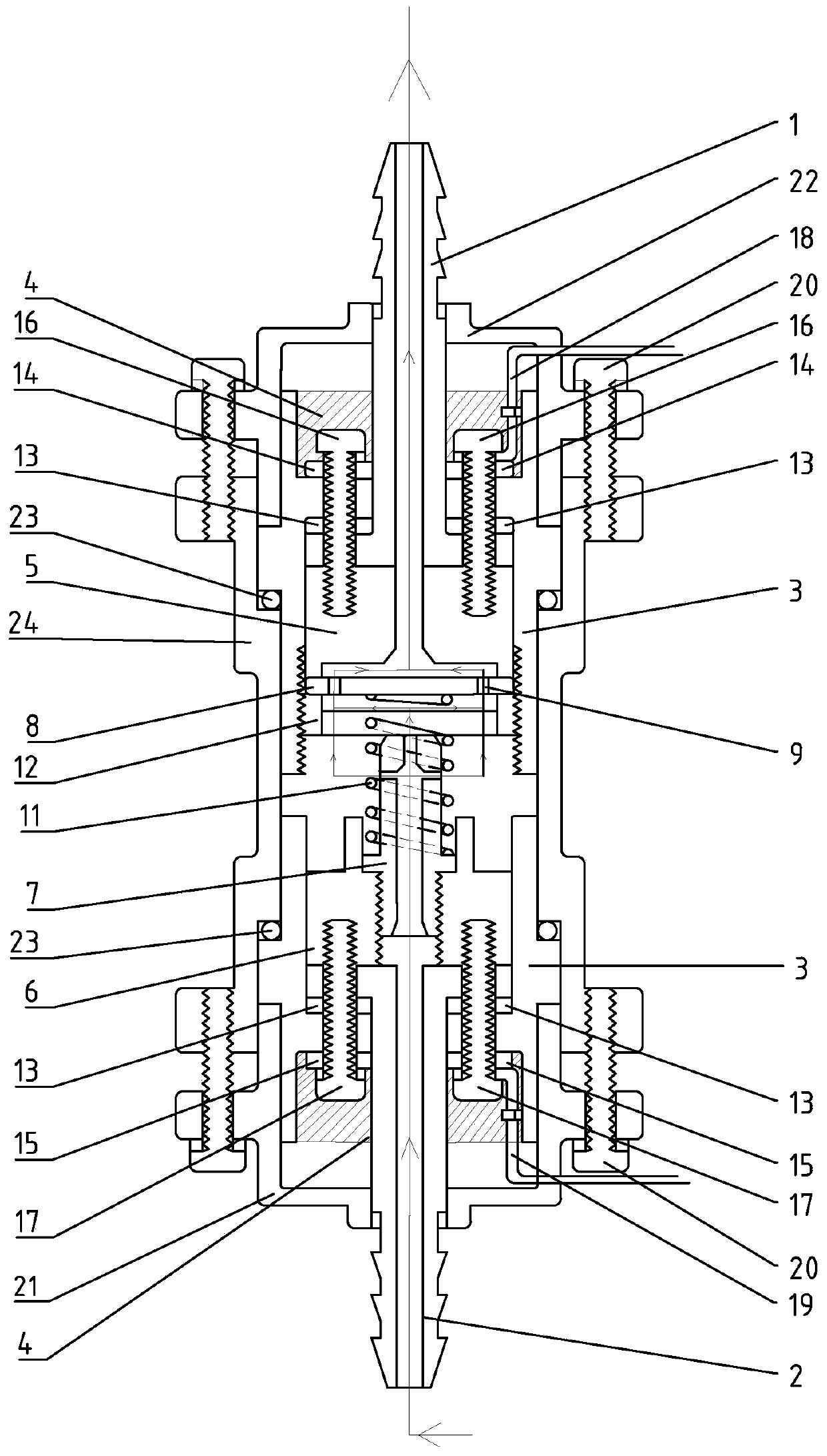
[0027] like figure 1 Shown is a standard ultrasonic fuel excitation device, that is, the ultrasonic transducer unit only includes one ultrasonic transducer sheet 8 .

[0028]The shell of the ultrasonic fuel excitation device is composed of an outer metal shell and an inner insulating shell, wherein the outer metal shell is composed of an inlet metal seal 21 , an outlet metal seal 22 and a metal shell 24 . The inlet metal seal 21 is fixed on the bottom of the metal shell 24 by two shell screws 20 , and the outlet metal seal 22 is fixed on the top of the metal shell 24 by the shell screws 20 . The inner insulating layer is composed of the inlet insulating oil nipple 2, the outlet insulating oil nipple 1 and the insulating shell 3. The inlet insulating nozzle 2 is hermetically arranged in the inlet metal head 21, and has a fuel inlet inside. The outlet insulating oil nozzle 1 is sealed and arranged in the outlet metal sealing head 22, and has a fuel outlet inside. The insulati...

Embodiment 2

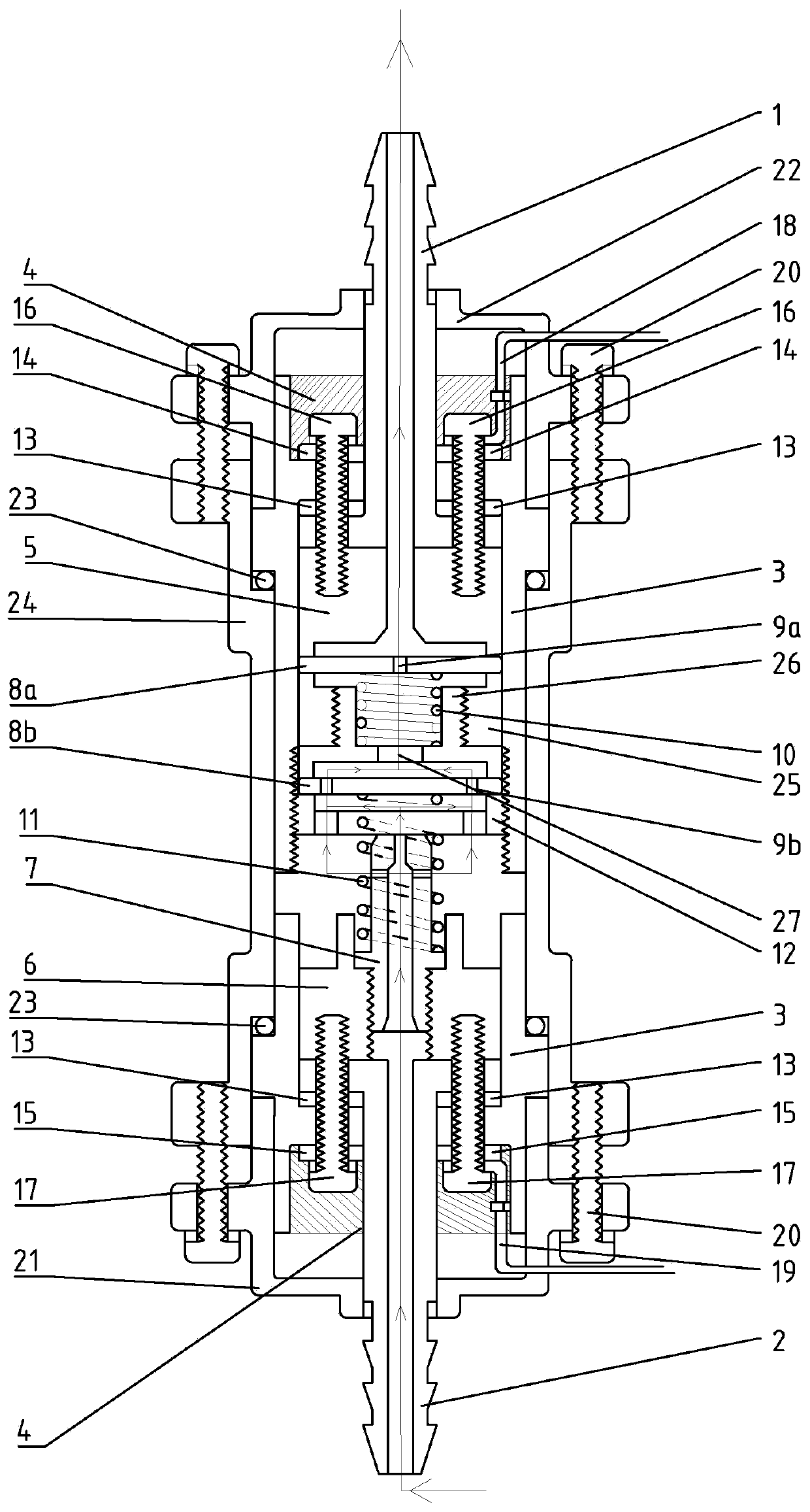
[0035] like figure 2 Shown is an enhanced ultrasonic fuel excitation device, that is, the ultrasonic transducer unit includes two ultrasonic transducers connected in series, namely a first ultrasonic transducer 8a and a second ultrasonic transducer 8b.

[0036] The shell of the ultrasonic fuel excitation device is composed of an outer metal shell and an inner insulating shell, wherein the outer metal shell is composed of an inlet metal seal 21 , an outlet metal seal 22 and a metal shell 24 . The inlet metal sealing head 21 is fixed on the bottom of the metal casing 24 by two casing screws 20 , and the outlet metal sealing head 22 is fixed on the top of the metal casing 24 by two casing screws 20 . The inner insulating layer is composed of the inlet insulating oil nipple 2, the outlet insulating oil nipple 1 and the insulating shell 3. The inlet insulating nozzle 2 is hermetically arranged in the inlet metal head 21, and has a fuel inlet inside. The outlet insulating oil noz...


PUM


Abstract

The invention discloses an ultrasonic fuel excitation device. The ultrasonic fuel excitation device comprises a shell, wherein the shell comprises an outer metal shell and an inner insulating layer, and an inner cavity filled with insulating liquid fuel, at least one fuel inlet and at least one fuel outlet are formed in the shell. The inner cavity of the shell at least comprises an ultrasonic transduction unit, a first electrode conductive connection block, a first conductive screw, a conductive spring, a second electrode conductive connection block and a second conductive screw. According tothe ultrasonic fuel excitation device, the fuel utilization rate can be increased, equipment power is enhanced, fuel is saved, emission of harmful gas is reduced, environment is protected, equipment running noise is reduced, oil paths are cleaned, carbon deposition is reduced, and installation and maintenance are easy. The ultrasonic fuel excitation device can be widely applied to equipment for acquiring energy through various fuels, and has strong adaptability.

Description

technical field [0001] The invention relates to an ultrasonic excitation device, in particular to an ultrasonic fuel excitation device. Background technique [0002] An engine is a mechanical device that uses some kind of fuel to generate power, that is, a machine that converts fuel into heat energy through chemical energy, and finally into mechanical energy. Engine efficiency has two indicators: mechanical efficiency and thermal efficiency. Among them, the thermal efficiency is the ratio of the heat used to do work after the fuel is burned to the total heat that can be generated. Part of the heat generated by the complete combustion of fuel is taken away by the engine cooling system, part of it is discharged with the exhaust gas, and only a small part of the heat is used to do work. The thermal efficiency of existing internal combustion engines is very low, generally 20% to 25% for four-stroke gasoline engines, and even for high-performance engines, its thermal efficiency...

Claims


Application Information

Patent Timeline
Patent Type & Authority Applications(China)
IPC IPC(8): F02M27/08F02M69/04
CPCF02M27/08F02M69/041Y02T10/12
Inventor 方荣武谈杰刘冀闽
Owner 方荣武
Why Eureka
Try Eureka