Argon microwave discharge plasma assisted methane and air swirling combustion device and method

A technology of microwave discharge and plasma, which is applied in the direction of combustion method, plasma, gas fuel burner, etc., can solve the complicated problems of swirl burner, achieve the effect of improving magnitude and dispersion, efficient combustion, and reducing loss

Pending Publication Date: 2019-07-19
SHANDONG NORMAL UNIV
View PDF0 Cites 8 Cited by
  • Summary
  • Abstract
  • Description
  • Claims
  • Application Information

AI Technical Summary

Problems solved by technology

[0007] (1) It is relatively simple to achieve a stable gas discharge at low pressure, but it is impossible to generate a large area of ​​uniform discharge plasma at atmospheric pressure
[0008] (2) The existing swirl burners are relatively complicated, and most of them require additional mechanical control components

Method used


Image

  • Argon microwave discharge plasma assisted methane and air swirling combustion device and method
  • Argon microwave discharge plasma assisted methane and air swirling combustion device and method
  • Argon microwave discharge plasma assisted methane and air swirling combustion device and method

Examples


Embodiment 1

[0042] This embodiment provides an argon microwave discharge plasma-assisted methane-air swirl combustion device. Through the synergistic effect of microwave discharge and swirl combustion, under atmospheric pressure conditions, the high-efficiency combustion of argon microwave discharge plasma-assisted methane-air mixture gas is realized. combustion.

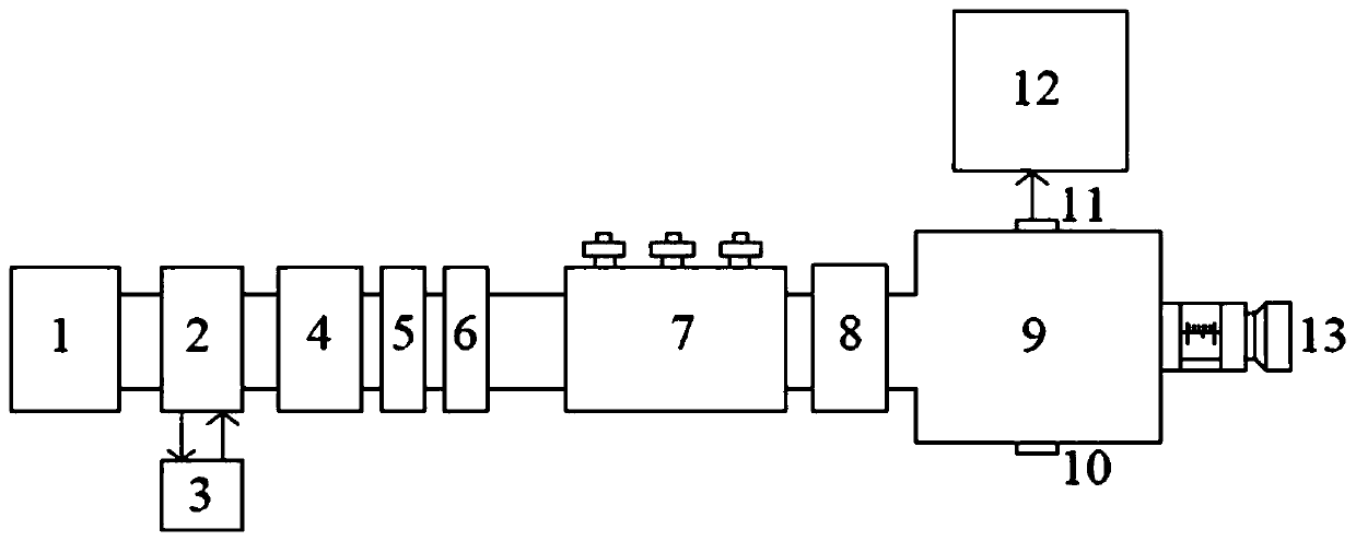
[0043] Please refer to the attached figure 1 , the argon microwave discharge plasma assisted methane air swirling combustion device includes a microwave power source 1, a microwave anti-reflux device, a three-pin adjuster 7, a conversion waveguide 8 and a microwave resonant cavity 9 connected in sequence, and the microwave power The source 1 drives the microwave discharge, and the microwave energy sequentially passes through the microwave anti-reflux device to isolate the reflected wave, the impedance matching of the three-pin adjuster 7 and the mode conversion of the conversion waveguide 8, and then enters the microwave resona...

Embodiment 2

[0060] This embodiment provides a working method of an argon microwave discharge plasma assisted methane air swirling combustion device, the method comprising the following steps:

[0061] S101, the microwave power source drives the microwave discharge to generate microwave energy;

[0062] S102, the microwave energy enters the microwave resonant cavity after sequentially passing through the microwave anti-reflux device to isolate the reflected wave, the impedance matching of the three-pin adjuster, and the converted waveguide mode conversion;

[0063] S103, the atmospheric pressure argon microwave discharge plasma is formed in the microwave resonant cavity and transported to the swirl burner;

[0064] S104, methane and air enter the swirl burner tangentially from the gas inlet alternately through the pressure reducing valve and the gas flow meter respectively;

[0065] S105, realizing stable combustion of methane and air in a swirl burner with the assistance of microwave arg...


PUM


Abstract

The invention discloses an argon microwave discharge plasma assisted methane and air swirling combustion device and method. Through the synergistic effect of microwave discharge and swirling combustion, under the condition of the atmospheric pressure, argon microwave discharge plasma assisted methane and air mixed gas efficient combustion is achieved. The argon microwave discharge plasma assistedmethane and air swirling combustion device comprises a microwave power source, a microwave anti-reflux device, a three-pin distributor, a conversion waveguide, a microwave resonant cavity and a swirling combustor; the microwave power source drives microwaves to discharge, and the microwaves sequentially pass through the microwave anti-reflux device, the three-pin distributor and the conversion waveguide and then enter the microwave resonant cavity to form atmospheric pressure argon microwave discharge plasma in the microwave resonant cavity; and methane and air tangently enter the swirling combustor through a gas inlet, and are combusted in the swirling combustor under assisting of the microwave argon discharge plasma.

Description

technical field [0001] The disclosure relates to an argon microwave discharge plasma assisted methane air swirl combustion device and method. Background technique [0002] The fossil energy crisis is an important issue facing the development of modern society. With the sharp reduction of fossil fuel reserves, how to efficiently use fossil fuels has become an important issue that human society needs to solve urgently. [0003] Lean Premixed Combustion (Lean Premixed Combustion) technology, as a high-efficiency, low-pollution combustion technology, has attracted extensive attention from researchers at home and abroad in recent years. Lean fuel premixed combustion with high thermal efficiency, CO and NO x Low emissions, good combustion economy and combustion effect. However, when the ratio of fuel to air approaches the lean burn limit (mass ratio of fuel to air 1:25), the energy required to start combustion increases, the flame propagation speed decreases, and the stability ...

Claims


Application Information

Patent Timeline
Patent Type & Authority Applications(China)
IPC IPC(8): F23D14/00F23D14/46H05H1/46
CPCF23D14/00F23D14/46H05H1/46H05H1/461
Inventor 潘杰陈晓晓杜军李时白成杰孙怡
Owner SHANDONG NORMAL UNIV
Why Eureka
Try Eureka