Measurement method and device of heliostat reflectivity

A measurement method and technology of a measurement device, which are applied in the measurement of scattering characteristics, color/spectral characteristics, etc., can solve the problems of heliostat reflectance measurement deviation, affecting the design and operation of solar power plants, etc., and achieve accurate measurement and no dependence on light sources. , measuring flexible effects

Active Publication Date: 2019-07-19
ZHEJIANG SUPCON SOLAR TECHNOLOGY CO LTD
View PDF11 Cites 3 Cited by
  • Summary
  • Abstract
  • Description
  • Claims
  • Application Information

AI Technical Summary

Problems solved by technology

This method relies heavily on the light source and requires the original intensity of the light source to be consistent throughout the shooting process. However, due to the impact of actual use and production of the current light source, the original intensity of the light source may be different at different times, which will lead to the measurement of the reflectivity of the heliostat. Deviation, and ultimately affect the design and operation of the entire solar power plant

Method used


Image

  • Measurement method and device of heliostat reflectivity
  • Measurement method and device of heliostat reflectivity
  • Measurement method and device of heliostat reflectivity

Examples


Embodiment 1

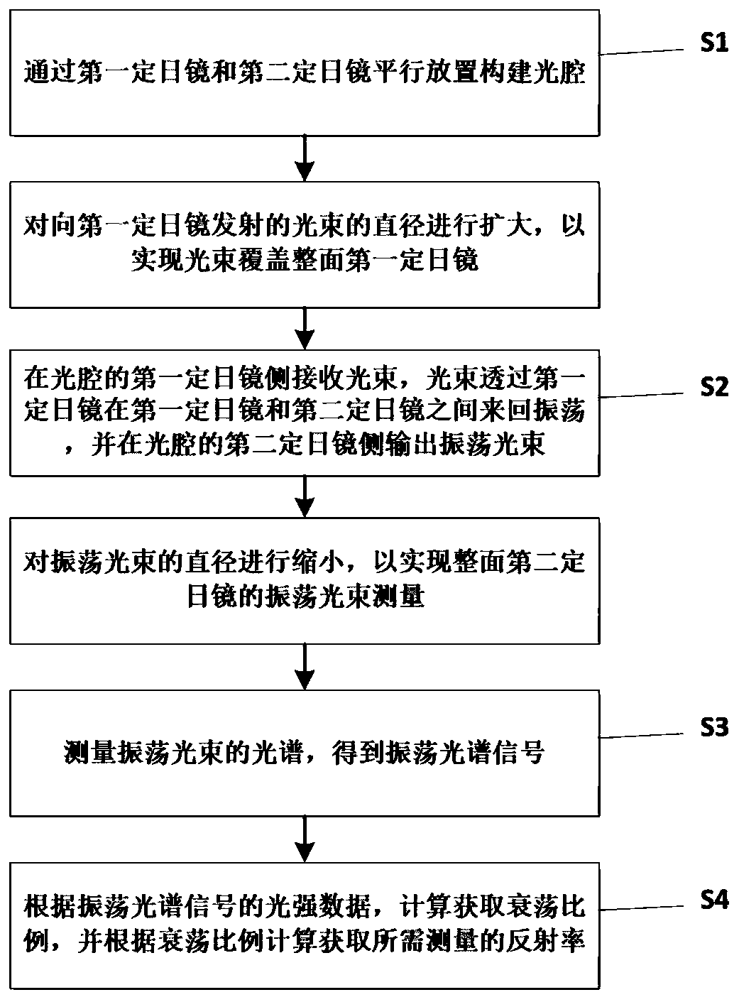
[0043] see figure 1 , the present embodiment provides a method for measuring the reflectivity of a heliostat, comprising the following steps:

[0044] S1: constructing an optical cavity by placing the first heliostat and the second heliostat in parallel;

[0045] S2: The light beam is received on the first heliostat side of the optical cavity, the light beam passes through the first heliostat and oscillates back and forth between the first heliostat and the second heliostat, and oscillates on the second heliostat of the optical cavity Side output oscillating beam;

[0046] S3: measuring the spectrum of the oscillating beam to obtain an oscillating spectrum signal;

[0047] S4: Calculate and obtain the ring-down ratio according to the light intensity data of the oscillation spectrum signal, and calculate and obtain the reflectance to be measured according to the ring-down ratio.

[0048] Now specifically describe this implementation in detail:

[0049]Specifically, the lig...

Embodiment 2

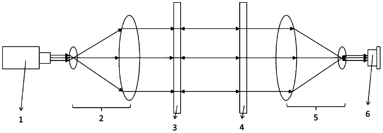
[0077] see figure 2 , the present embodiment provides a heliostat reflectivity measurement device based on Embodiment 1, including: a pulsed light source 1, a beam expander module 2, an optical cavity, a beam shrinker module 5, a spectrum receiving module 6, and a data processing module;

[0078] The beam expansion module 2 is used to expand the diameter of the original beam emitted by the pulse light source 1, and output the expanded beam;

[0079] The optical cavity includes a first heliostat 3 and a second heliostat 4 arranged parallel to each other. The optical cavity is used for the back-and-forth oscillation of the beam, wherein the optical cavity receives the expanded beam on the side of the first heliostat 3, and the expanded beam Through the first heliostat 3, oscillate back and forth between the first heliostat 3 and the second heliostat 4, and output the oscillating beam on the side of the second heliostat 4, wherein the expanded beam covers the first heliostat mi...


PUM


Abstract

The invention discloses a measurement method and device of heliostat reflectivity. The measurement method comprises the steps that S1, an optical cavity is constructed by parallel placement of a firstheliostat and a second heliostat; S2, a beam is received on the first heliostat side of the optical cavity and oscillates back and forth between the first heliostat and the second heliostat through the first heliostat, and an oscillating beam is output on the second heliostat side of the optical cavity; S3, the spectrum of the oscillating beam is measured, and oscillating spectrum signals are obtained; and S4, according to intensity data of the oscillating spectrum signals, the attenuation ratio is calculated and obtained, and the reflectivity need to be measured is obtained according to theattenuation ratio. Because the method can measure the reflectivity of the heliostats by measuring the attenuation ratio of light intensity, the stability of light source is not required, additional calibration work is not needed, and the measurement method has the technical characteristics of accurate, fast, direct and light source-independent reflectivity measurement.

Description

technical field [0001] The invention belongs to the technical field of tower-type solar thermal power plants, and in particular relates to a method and device for measuring the reflectivity of a heliostat. Background technique [0002] With the development of the economy, the depletion of fossil fuels and the aggravation of environmental pollution, the energy issue has gradually been paid attention to by people. At the same time, due to the increasing complexity of international relations, energy security has also become one of the looming problems. As a new energy source, solar energy has received increasing attention from the state in recent years. Solar thermal power generation is considered to be one of the most potential power generation methods due to its stable output, controllable energy storage and other reasons. image 3 It is a schematic diagram of the structure of the tower solar thermal power generation system. Its basic form is to heat the working medium through...

Claims


Application Information

Patent Timeline
Patent Type & Authority Applications(China)
IPC IPC(8): G01N21/55G01N21/31
CPCG01N21/55G01N21/31
Inventor 颜明明李晓波刘志娟杨都堂宓霄凌张先竹
Owner ZHEJIANG SUPCON SOLAR TECHNOLOGY CO LTD
Why Eureka
Try Eureka