Small-angle light-splitting light engine device and rapid mounting and adjusting method thereof

A small-angle, light-splitting technology, applied in measurement devices, instruments, utilization of re-radiation, etc., can solve problems such as unfavorable system miniaturization, modular design and integration, inconvenient access to auxiliary facilities, and large space for the overall optical path. The debugging method and process are intuitive, the long-term work stability is enhanced, and the optical-mechanical structure is concise.

Active Publication Date: 2019-07-19
WUHAN UNIV
View PDF11 Cites 1 Cited by
  • Summary
  • Abstract
  • Description
  • Claims
  • Application Information

AI Technical Summary

Problems solved by technology

However, the discrete optical layout scheme and fine mechanical adjustment mechanism often lead to a large space occupied by the overall optical path (for example, the length can reach the order of meters); the biggest defect is that the installation and adjustment process is more troublesome, and various auxiliary adjustment devices need to be introduced and professional testing tools, and it is inconvenient to access auxiliary facilities
Therefore, the use of existing technologies is not conducive to improving the long-term stability of the overall system (especially under the application conditions of mobile field experiments), and is also not conducive to the miniaturization, modular design and integration of the system. Inconvenience

Method used


Image

  • Small-angle light-splitting light engine device and rapid mounting and adjusting method thereof
  • Small-angle light-splitting light engine device and rapid mounting and adjusting method thereof

Examples


Embodiment Construction

[0024] The technical solutions of the present invention will be described in detail below in conjunction with the accompanying drawings and embodiments.

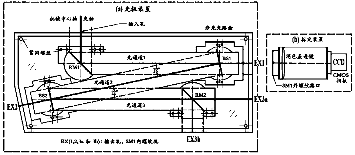
[0025] see figure 1 , the small-angle spectroscopic optical-mechanical device provided by the embodiment of the present invention is composed of an optical-mechanical device and a calibration device,

[0026] The optical-mechanical device is the main part of the invention, including a splitting optical path box and a beam-guiding element, which are combined to realize efficient separation of target signals from various channels. The calibration device is an auxiliary part of the invention, including an SM1 external thread interface, an achromatic lens and a CMOS camera, and is used to quickly adjust each beam guiding element in the optomechanical device to a predetermined working state.

[0027] The light-splitting optical box includes an input hole, an optical channel 1, an optical channel 2 and an optical channel 3, and o...


PUM


Abstract

The invention discloses a small-angle light-splitting light engine device and a rapid mounting and adjusting method thereof. The small-angle light-splitting light engine device is composed of a lightengine device body and a calibration device; the light engine device body comprises a light-splitting light path box and light beam guiding elements, the light beam guiding elements are arranged in the light-splitting light path box, and the light-splitting light path box and the light beam guiding elements are combined to efficiently separate and output a target input compound color light signal;and the calibration device comprises an external threaded interface, an achromatic lens and a CMOS camera for assisting in quickly adjusting all the light beam guiding elements in the light engine device body to the predetermined working state. The light engine device is integrally designed, has the advantages of small size, concise light engine structure, convenient connection and the like, is very effective for separation of the compound color light signal, close to the nm magnitude, on a frequency spectrum, and can be applied in the development process of a rotating Raman laser radar system.

Description

technical field [0001] The invention belongs to the field of laser radar, and in particular relates to an optical-mechanical device for separating target optical signals by using a light-splitting device with a small working angle, and a method for quickly installing and adjusting the device. Background technique [0002] Rotating Raman lidar is an effective detection method for remote sensing of low-altitude atmospheric temperature. The temperature measurement principle of the rotating Raman lidar is that under the condition of local heat balance, the layout number of atmospheric molecules satisfies the Boltzmann distribution (Boltzmann distribution), and then the atmospheric molecules (mainly N 2 and O 2 The intensity of the rotational Raman line generated by the molecule) is temperature dependent. The temperature can be directly inverted by extracting two Raman echo signals with opposite temperature dependence for comparison, and establishing the relationship between th...

Claims


Application Information

Patent Timeline
Patent Type & Authority Applications(China)
IPC IPC(8): G01S17/02G01S7/481
CPCG01S7/4816G01S17/02
Inventor 柳付超易帆张云鹏余长明易洋潘向亮
Owner WUHAN UNIV
Why Eureka
Try Eureka