Drilling device for automatic feeding

A technology of drilling equipment and automatic feeding, which is used in drilling/drilling equipment, boring/drilling, metal processing equipment, etc. To improve the accuracy of punching, eliminate positioning errors, and ensure quality

Active Publication Date: 2019-07-23
济南希润自动化科技有限公司
View PDF8 Cites 0 Cited by
  • Summary
  • Abstract
  • Description
  • Claims
  • Application Information

AI Technical Summary

Problems solved by technology

[0003] Most of the existing drilling machines use manual loading, and moving the raw materials manually not only consumes a lot of labor, but also the raw materials are usually heavy, and the movement of the manual moving raw materials is slow, which affects the production efficiency. On the other hand, in the back and forth In the process of moving raw materials, it will not only bring losses to the raw materials, but also easily change the positioning reference, which will cause positioning errors, lead to the deviation of the drilling position, and reduce the quality of the product. Therefore, in view of the above status quo, it is urgent to develop a A kind of automatic feeding drilling equipment to overcome the deficiencies in the current practical application

Method used


Image

  • Drilling device for automatic feeding
  • Drilling device for automatic feeding
  • Drilling device for automatic feeding

Examples


Embodiment 1

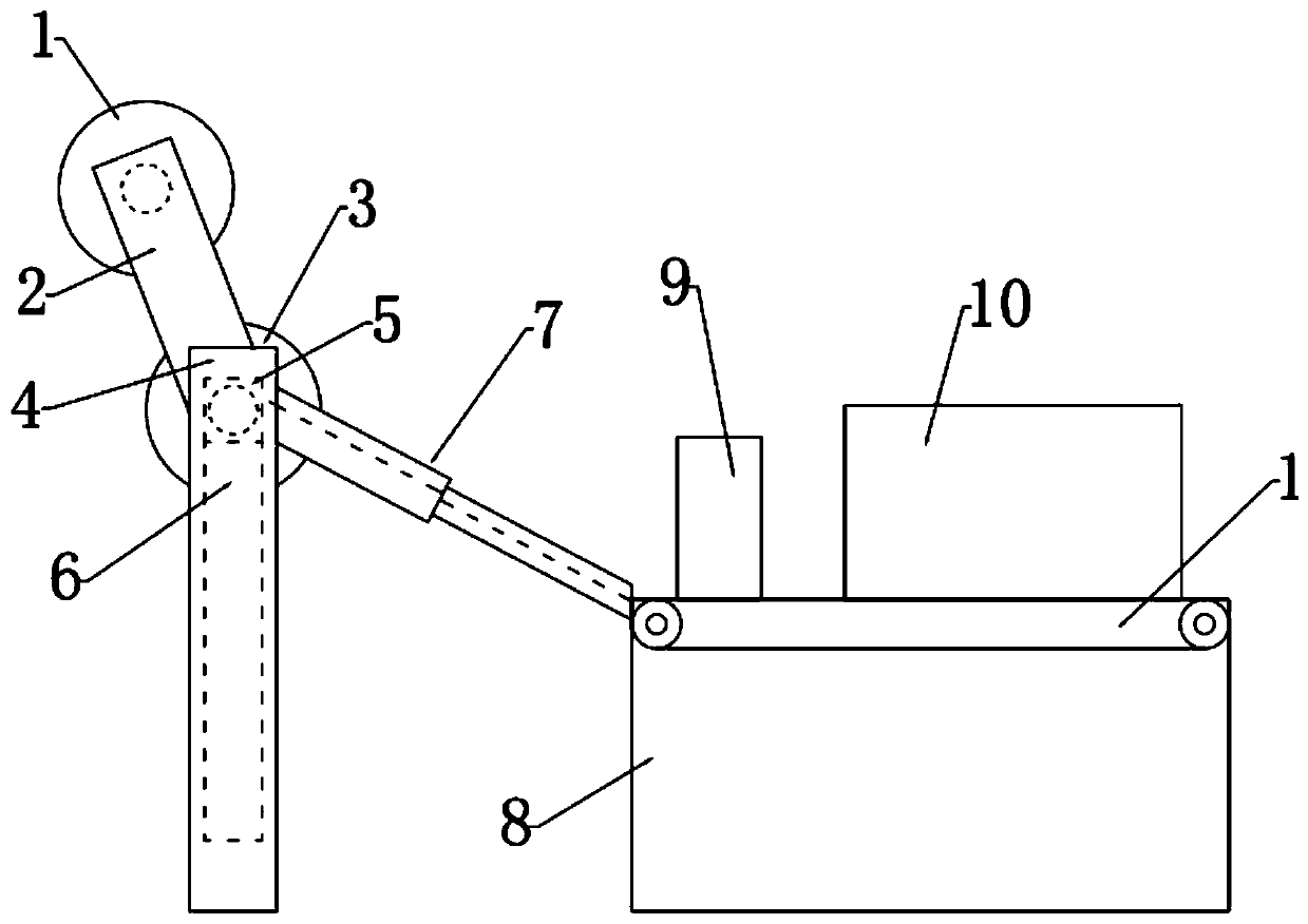
[0031] see Figure 1~4 , in the embodiment of the present invention, an automatic feeding drilling equipment includes a base 8, a feeding mechanism is provided on the left side of the base 8, and the feeding mechanism and the base 8 are connected by a conveying mechanism 7, so The top of the base 8 is fixedly connected with a fixing mechanism 9, the right side of the fixing mechanism 9 is provided with a protective shell 10 fixedly connected with the base 8, the inside of the protective shell 10 is provided with a punching mechanism, and the lower side of the punching mechanism A conveyor belt 11 is provided.

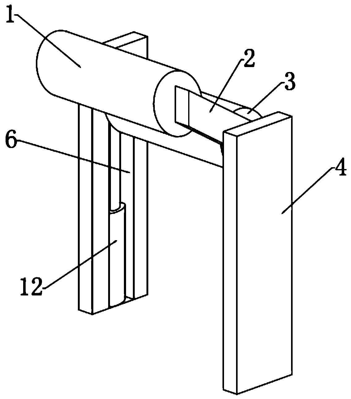
[0032] In this embodiment, the feeding mechanism includes a first conveying roller 1, a connecting rod 2, a second conveying roller 3, a support column 4, a slider 5, a slide rail 6 and a first telescopic rod 12, and the support column 4 It is arranged on the left side of the base 8, and the second transmission roller 3 is arranged between the support columns 4 on the ...

Embodiment 2

[0041] A drilling mechanical equipment, comprising the automatic feeding drilling equipment described in Embodiment 1.

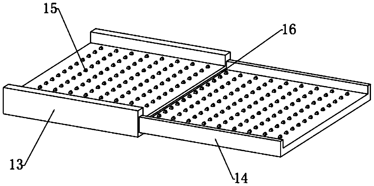
[0042] The automatic feeding drilling equipment can make the first conveying roller 1 contact with the raw material and drive the material to move to the right, and pass through the second conveying roller 3. Make the material fall into the conveying mechanism 7, realize the automatic feeding of raw materials, reduce the labor consumption, and improve the production efficiency. By setting the conveying mechanism 7, the material can be avoided to move back and forth, thereby eliminating the positioning error and improving the drilling efficiency. Accuracy, by adopting the conveying wheel 15 of rubber material, it can play the role of shock absorption and buffering, and at the same time, it can protect the surface of the raw material. By setting the fixing device, the raw material can be fixed horizontally, avoiding the side slip of the raw material Set fixed ...


PUM


Abstract

The invention relates to the technical field of drilling mechanical equipment and specifically provides a drilling device for automatic feeding. The drilling device comprises a base, wherein a feedingmechanism is disposed on the left side of the base; the feeding mechanism and the base are connected by a conveying mechanism; a fixation mechanism is disposed on the top of the base; a protection shell is disposed on the right side of the fixation mechanism; a drilling mechanism is disposed inside the protection shell; and a conveying belt is disposed on the lower side of the drilling mechanism.The drilling device disclosed by the invention has the beneficial effects that a first transmission roller and a second transmission roller can be disposed in a staggered manner; the first transmission roller touches raw materials and drives the materials to move to the right; the second transmission roller can drive the materials to fall onto the conveying mechanism, so automatic feeding of theraw materials is realized and production efficiency is increased; an air outlet pipe, an air inlet pipe and a fan are disposed, so dust generated during drilling can be blown by the air outlet pipe tothe right side of the protection shell and the dust blown to the right side is absorbed by the air inlet pipe, and thus the dust generated during drilling can be processed effectively.

Description

technical field [0001] The invention relates to the technical field of drilling machinery and equipment, in particular to drilling equipment for automatic feeding. Background technique [0002] Drilling machine is a general term for machinery and equipment that uses a tool that is harder and sharper than the target to leave a cylindrical hole or hole on the target by means of rotary cutting or rotary extrusion. Also known as drilling rigs, punching machines, drilling machines, through-hole machines, etc. [0003] Most of the existing drilling machines use manual loading, and moving the raw materials manually not only consumes a lot of labor, but also the raw materials are usually heavy, and the movement of the manual moving raw materials is slow, which affects the production efficiency. On the other hand, in the back and forth In the process of moving raw materials, it will not only bring losses to the raw materials, but also easily change the positioning reference, which w...

Claims


Application Information

Patent Timeline
Patent Type & Authority Applications(China)
IPC IPC(8): B23B39/00B23B47/20B23B47/06B23Q11/00
CPCB23B39/00B23Q5/10B23Q5/28B23Q11/005
Inventor 任航萱
Owner 济南希润自动化科技有限公司
Why Eureka
Try Eureka