Offset Steering Mechanism and Control Method of Static Pointing Rotary Steerable Drilling Tool

A technology of rotary steerable drilling and steering mechanism, which is used in directional drilling, driving devices for drilling in wellbore, drilling equipment, etc., can solve the problems of high drilling fluid sealing requirements, deformation, and difficulty in increasing precise hydraulic steering control.

Active Publication Date: 2021-05-04
CHINA UNIV OF PETROLEUM (EAST CHINA)
View PDF6 Cites 0 Cited by
  • Summary
  • Abstract
  • Description
  • Claims
  • Application Information

AI Technical Summary

Problems solved by technology

Its shortcomings are as follows: ①The guiding function of this case is realized by the flexible mandrel, which needs to withstand high-intensity alternating stress, which is prone to fatigue damage; ②The double eccentric ring bias mechanism of this case is driven by harmonics Driven by the mechanism, the flexible parts in the harmonic drive mechanism will be periodically deformed and easily damaged by fatigue; ③The braking effect of this case is realized by the electromagnetic clutch corresponding to the inner ring and the outer ring, because an additional design is required to match the bias mechanism braking device, increasing the complexity of the system
Its shortcomings are: ① Motor vector control is a method of dynamically adjusting the direction of the drill bit. This method is relatively complicated, and the control effect will be affected by the disturbance caused by the drill bit during the drilling process; The method for the braking device to lock the position of the eccentric ring will increase the complexity of the system, and the case does not elaborate on the structure of the braking device
Its shortcoming is that the guiding control of the solenoid valve belongs to the method of dynamically adjusting the direction of the drill bit, and the guiding effect will be affected by the interference brought by the drill bit, so it is difficult to realize precise guiding control
The disadvantage is that the hydraulic pump in this system is powered by drilling fluid, and the fluctuation of drilling fluid pressure will affect the steering effect, which increases the difficulty of precise hydraulic steering control
The disadvantage is that the hydraulic control system is easily affected by the pressure of the drilling fluid, and multiple components are in contact with the drilling fluid, the service life will be affected, and the sealing requirements for the drilling fluid are high
[0010] At present, the existing technology has the following defects that need to be solved urgently: ①The motor control method based on the double eccentric ring structure and the servo valve control method based on the hydraulic system are both dynamic guidance methods, and the control method is relatively complicated and will be disturbed by the drill bit ②The braking function of the bias mechanism is realized by additional braking devices, such as the clutch of the double eccentric ring, the brake of the motor, and the self-locking mechanism of the gear transmission, which increase the complexity of the system; ③ When the offset steering mechanism based on double eccentric rings is driven by a harmonic drive mechanism, the flexible parts in the harmonic drive mechanism are prone to fatigue damage; ④ The design of the offset steering mechanism based on hydraulic control needs to consider the sealing of the drilling fluid, and Drilling Fluid Pressure Fluctuation Affects Steering Control

Method used


Image

  • Offset Steering Mechanism and Control Method of Static Pointing Rotary Steerable Drilling Tool
  • Offset Steering Mechanism and Control Method of Static Pointing Rotary Steerable Drilling Tool
  • Offset Steering Mechanism and Control Method of Static Pointing Rotary Steerable Drilling Tool

Examples


Embodiment Construction

[0045] The preferred embodiments of the present invention will be described in detail below in conjunction with the accompanying drawings; it should be understood that the preferred embodiments are only for illustrating the present invention, rather than limiting the protection scope of the present invention.

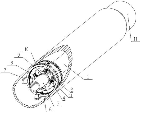
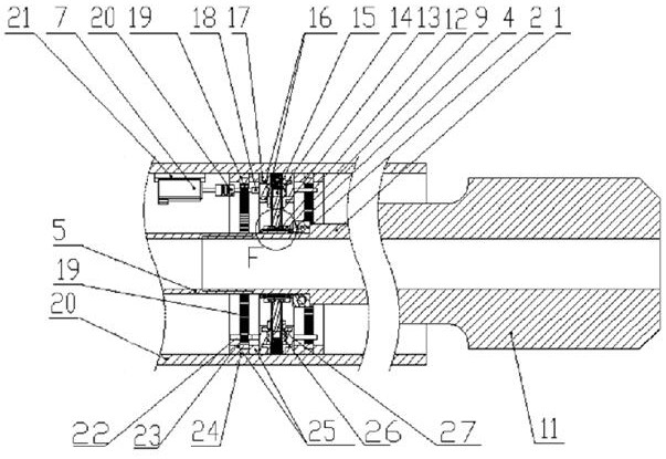
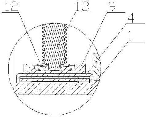
[0046] Such as Figure 1 to Figure 3 As shown, the offset guide mechanism of the static pointing rotary steerable drilling tool includes a non-rotating outer cylinder 10, a drill bit 11, a drill bit connecting shaft 1, a flexible hose 5, a slider connector 9, a guide mechanism housing 17 and a bias mechanism , The biasing mechanism is provided with two groups, and is installed in the non-rotating outer cylinder 10 perpendicular to each other, and the adjustment directions of the two biasing mechanisms are the X direction and the Y direction.

[0047] Specifically, the drill bit connecting shaft 1 is a hollow body, and the hollow part is used as a circulation channel for...


PUM


Abstract

The invention discloses an offset guiding mechanism and a control method of a static pointing rotary steering drilling tool, which belongs to the technical field of oil and gas drilling, and includes a drill bit connecting shaft and a non-rotating outer cylinder. The guiding mechanism also includes a flexible hose, a biasing The flexible hose is connected to the connecting shaft of the drill bit. The biasing mechanism is installed in the non-rotating outer cylinder. The biasing mechanism includes an aligning slider, a spiral telescopic mechanism, and a control motor. The slider The connecting piece is set outside the connecting shaft of the drill bit. The self-aligning slider is connected with the control motor through a spiral telescopic mechanism and installed in the slider connecting piece. The self-aligning slider moves forward and backward driven by the control motor, pushing The drill bit is connected to the shaft to realize the control of the structure bending angle and the tool face angle. The disturbance in the single connection process and the load applied to the motor are small and relatively stable, the system's demand for electric energy is significantly reduced, and the service life of the guide tool is improved; the scheme is simple and easy to implement, and the structure is compact.

Description

technical field [0001] The invention belongs to the technical field of oil and gas drilling, and in particular relates to an offset guiding mechanism and a control method of a static pointing rotary steering drilling tool. Background technique [0002] Rotary steerable drilling tools represent the highest level of development of petroleum directional drilling tools. Rotary steerable drilling tools can be divided into pushing type and pointing type according to the action mode of the steering mechanism, and can be divided into dynamic type and static type according to whether the outer cylinder of the steering tool rotates. The push-on type refers to the interaction between the steering mechanism and the well wall, and the direction of the drill bit is controlled by the generated reaction force. This method will produce a spiral wellbore, and its steering ability is limited by the formation structure, and its steering ability in soft formations is poor; The type means that t...

Claims


Application Information

Patent Timeline
Patent Type & Authority Patents(China)
IPC IPC(8): E21B7/04E21B4/04
CPCE21B4/04E21B7/04
Inventor 耿艳峰杨毅森王伟亮杨成永程民彪贾梦之
Owner CHINA UNIV OF PETROLEUM (EAST CHINA)
Why Eureka
Try Eureka