Mirror ratchet mutually-standby hand cranking power generation mechanism and non-power-source electronic lock

A technology of manual power generation and ratchet mechanism, which is applied in the direction of machines/engines, locks operated by non-mechanical transmission, mechanisms that generate mechanical power, etc., and can solve the problem of increasing the circuit complexity of passive electronic locks, user inconvenience, and manual charging mechanisms Inability to use inertial energy and other issues to achieve the effect of dual power output, simplified circuit, and easy to use

Pending Publication Date: 2019-07-23
广州启懿实业有限责任公司
View PDF1 Cites 2 Cited by
  • Summary
  • Abstract
  • Description
  • Claims
  • Application Information

AI Technical Summary

Problems solved by technology

[0004] 1. When in use, it is necessary to carry an inductive power supply to supply power to the control system through the inductive charging module, but the carrying of the inductive power supply brings inconvenience to the user;
[0005] 2. The power supply on one side needs to be electrically connected to two sets of control system

Method used


Image

  • Mirror ratchet mutually-standby hand cranking power generation mechanism and non-power-source electronic lock
  • Mirror ratchet mutually-standby hand cranking power generation mechanism and non-power-source electronic lock
  • Mirror ratchet mutually-standby hand cranking power generation mechanism and non-power-source electronic lock

Examples


Embodiment Construction

[0032] The present invention is further described below in conjunction with embodiment.

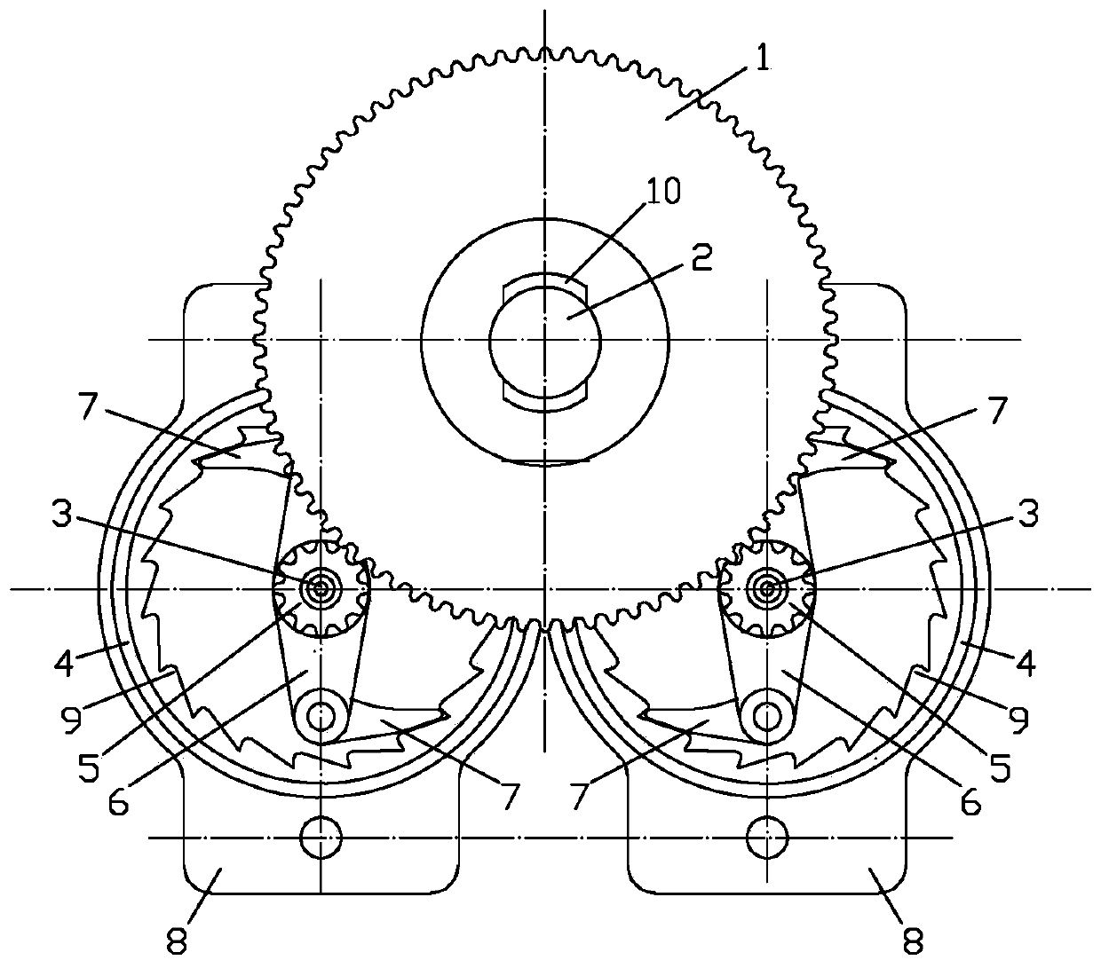
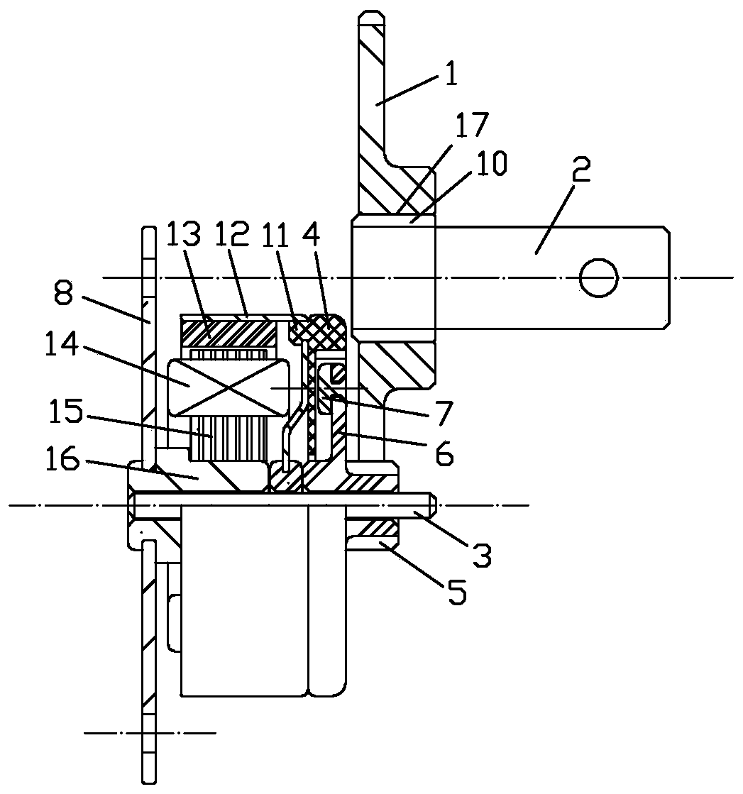
[0033] Such as figure 1 and figure 2 Shown is the mirror image ratchet mutual backup type manual power generation mechanism of this embodiment, which includes a casing (not shown in the figure), a driving gear 1, a handle shaft 2 and two power generating mechanisms, and the driving gear is rotatably supported on the casing , the handle rotating shaft is connected with the driving gear, and the driving gear is driven to rotate through the handle rotating shaft, and the two power generating mechanisms are symmetrically arranged left and right relative to the driving gear.

[0034] The power generation mechanism includes a driven gear 5, a ratchet mechanism, a generator and a fixed plate 8. The generator is installed on the fixed plate 8 on the casing, and the driven gear 5 is connected with the rotor of the generator through a ratchet mechanism, thereby realizing one-way drive The rotor ...


PUM


Abstract

The invention discloses a mirror ratchet mutually-standby hand cranking power generation mechanism which comprises a shell, a drive gear, a handle rotating shaft and two power source generation mechanisms. The drive gear is rotationally supported on the shell. The handle rotating shaft is connected with the drive gear. The two power source generation mechanisms are symmetrically arranged in the left-right direction. Each power generation mechanism comprises a drive gear, a ratchet mechanism, a power generator and a fixing plate. The power generators are installed on the fixing plates. The twodriven gears are engaged with the drive gear and are connected with rotors of the power generators through ratchet mechanisms correspondingly. By means of the power generation mechanism, double-power-source output is achieved. The invention further discloses a non-power-source electronic lock which comprises a shell, a rotating handle, a lock cylinder, a circuit board and the mirror ratchet mutually-standby hand cranking power generation mechanism. The mirror ratchet mutually-standby hand cranking power generation mechanism is installed in the shell, the rotating handle is installed on the handle rotating shaft, and the power output ends of the two power generators are electrically connected with two sets of control systems of a circuit board correspondingly. By means of the non-power-source electronic lock, a circuit is simplified.

Description

technical field [0001] The invention relates to a mirror image ratchet mutual backup type manual power generating mechanism, and also relates to a passive electronic lock using the mirror image ratchet mutual backup type manual power generation mechanism for power supply. Background technique [0002] The passive electronic locks currently on the market are to transfer the power of the lock to the key of the electronic lock. The operation of unlocking is the process of the key supplying power to the lock and mutual access. This is exactly in line with people's daily habits. After the work is over, the key can be connected to the background to upload the record, and indirectly achieve the same as the access control system, saving the opening and closing records of the relevant objects. [0003] The Chinese patent application number 201611129600.3 discloses a self-powered passive electronic lock, which adopts a dual power supply structure, one of which is generated by a manua...

Claims


Application Information

Patent Timeline
IPC IPC(8): F03G5/02E05B47/00
CPCF03G5/02E05B47/0001E05B2047/0062
Inventor 庞立峰袁海明陈敏
Owner 广州启懿实业有限责任公司
Why Eureka
Try Eureka