Fatigue testing machine capable of applying complex coupling force and its control circuit
A fatigue testing machine and fatigue testing technology, applied in the field of fatigue testing machines, can solve the problems of large volume, difficult movement and high cost, and achieve the effect of simplifying the testing process, avoiding repeated handling and avoiding damage
- Summary
- Abstract
- Description
- Claims
- Application Information
AI Technical Summary
Problems solved by technology
Method used
Image
Examples
Embodiment 1
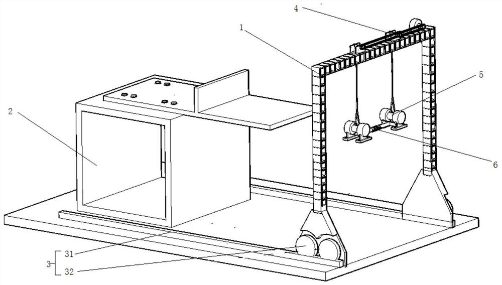
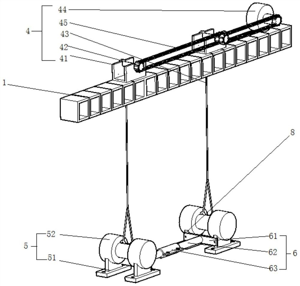
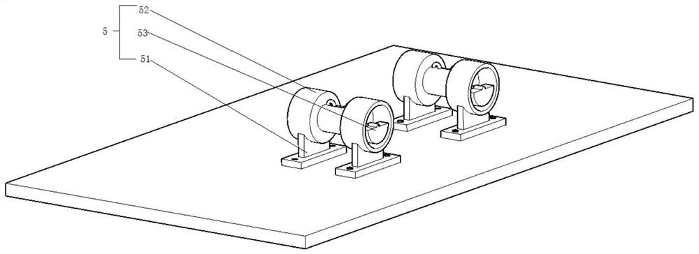
[0021] Such as figure 1 As shown, a fatigue testing machine capable of applying complex coupling forces includes a gantry 1, and a specimen fixing frame 2 is provided between the two vertical arms of the gantry 1; The horizontal slideway mechanism 3 at the distance between the gantry 1 and the specimen fixing frame 2, the vertical arm of the gantry 1 is provided with a vertical lifting mechanism 4, and the vertical lifting mechanism 4 is provided with a fatigue test power mechanism 5, and the fatigue test power The mechanism 5 is provided with a spacing adjustment mechanism 6; it also includes a testing machine control system 7 (not marked in the figure) for controlling the vertical lifting mechanism 4, the fatigue test power mechanism 5 and the spacing adjustment mechanism 6 to work.
[0022] The horizontal slideway mechanism 3 includes rails 31 that are left and right opposite on the bottom surface and rollers 32 arranged on the bottom of the gantry 1. The gantry 1 moves alo...
Embodiment 1-1
[0032] Example 1-1: Effect of variable amplitude loading
[0033] Close S1 and S2, open S3, the two vibration motors 52 are connected in parallel, and the frequency modulation circuit, phase angle circuit and steering circuit can be adjusted arbitrarily, so that the vibration curves of the two motors 44 can be superimposed arbitrarily to form a variable amplitude loading effect. Strain gauges are arranged at the measured position, and the time-history strain in the test process is obtained through strain monitoring. The fatigue stress spectrum is obtained by rainflow counting method, that is, different stress amplitudes and their corresponding cycle times are applied to the specimen under variable amplitude loading. research on fatigue performance.
Embodiment 1-2
[0034] Example 1-2: Bending moment action
[0035] Close S3, open S1 and S2, and connect the two vibration motors 52 in series; respectively adjust the frequency modulation circuit and the phase angle circuit to keep the vibration frequency and phase angle of the two motors 44 consistent. Adjust the steering circuit, and set the steering of the centrifugal blocks 53 of the two vibrating motors 52 to reverse; the rotation direction of the motor eccentric blocks and the force generated on the test piece can be seen Figure 6 , the same vertical force produces a bending moment, and the opposite horizontal forces cancel each other out, thus forming a bending moment in the weld. Strain gauges are arranged at the measured position, and the normal stress of the tested part of the test piece is obtained through strain monitoring. To study the fatigue performance of the specimen under the action of bending moment, the formula is:
[0036] M=2mπfr 2 L 1
[0037] Wherein, the bendin...
PUM
 Abstract
Description
Claims
Application Information
 - R&D
- Intellectual Property
- Life Sciences
- Materials
- Tech Scout
- Unparalleled Data Quality
- Higher Quality Content
- 60% Fewer Hallucinations
Browse by: Latest US Patents, China's latest patents, Technical Efficacy Thesaurus, Application Domain, Technology Topic, Popular Technical Reports.
© 2025 PatSnap. All rights reserved.Legal|Privacy policy|Modern Slavery Act Transparency Statement|Sitemap|About US| Contact US: help@patsnap.com


