Elliptical waveguide load

An elliptical waveguide and waveguide cavity technology, which is applied to waveguide devices, electrical components, circuits, etc., can solve the problems of increasing the complexity of components, and achieve the effects of saving installation space, excellent VSWR performance, and reducing costs

Pending Publication Date: 2019-07-23
上海传输线研究所
View PDF0 Cites 0 Cited by
  • Summary
  • Abstract
  • Description
  • Claims
  • Application Information

AI Technical Summary

Problems solved by technology

[0004] On the one hand, the elliptical-rectangular converter solves the problem of matching the elliptical interface with the standard interface, but on the other hand, it also increases the complexity of the components and introduces additional reflection and insertion loss

Method used


Image

  • Elliptical waveguide load
  • Elliptical waveguide load
  • Elliptical waveguide load

Examples


Embodiment 1

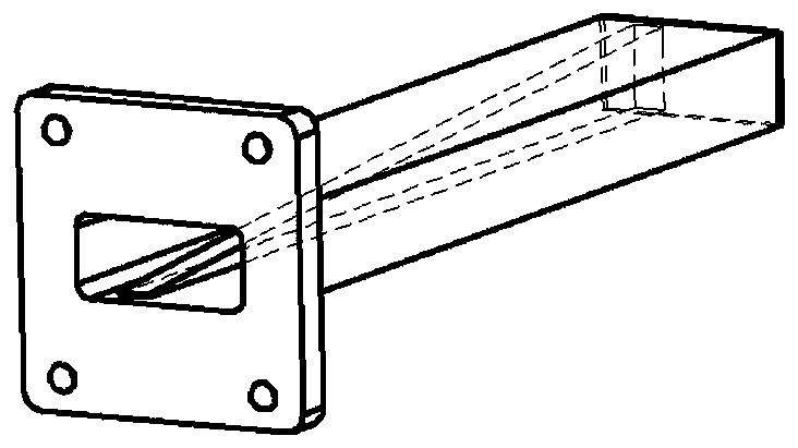
[0030] 1) Structure: The elliptical waveguide load is composed of a flange 1, a waveguide cavity 2, an absorber 3 and a tail cover 4. The cross section of the waveguide cavity 2 is elliptical, and the absorber 3 is a cone. The angle is 5°, and the length of the absorber 3 is taken as 2 times of λ / 2.

[0031] 2) Material: the flange, the waveguide cavity and the tail cover are made of duralumin LY12; the absorber is made of bakelite; the outer surface of the elliptical waveguide load is anodized.

[0032] 3) Dimensions: the ratio of the minor axis to the major axis of the elliptical section of the waveguide cavity 2 is 0.45.

[0033] 4) Assembly: the flange is connected to one end of the waveguide cavity by silver soldering; the conical bottom surface of the absorber is connected to the tail cover through adhesive, and the sticking position should be slightly away from the left side of the center of the tail cover by 5mm; the tail cover after the glue is completed The plate is...

Embodiment 2

[0036] 1) Structure: The elliptical waveguide load is composed of a flange 1, a waveguide cavity 2, an absorber 3 and a tail cover 4. The cross section of the waveguide cavity 2 is elliptical, and the absorber 3 is a cone. The angle is 15°, and the length of the absorber 3 is taken as 4 times of λ / 2.

[0037] 2) Material: The flange, waveguide cavity and tail cover are made of environmentally friendly copper (C3604), and the outer surface is nickel-plated; the absorber is made of conductive fiber.

[0038] 3) Dimensions: the ratio of the minor axis to the major axis of the elliptical section of the waveguide cavity 2 is 0.65.

[0039] 4) Assembly: The flange is connected to one end of the waveguide cavity by silver soldering; the conical bottom surface of the absorber is connected to the tail cover through adhesive, and the sticking position should be slightly away from the right side of the center of the tail cover by 8mm; the tail cover after the glue is completed The plate...

Embodiment 3

[0041] 1) Structure: The elliptical waveguide load is composed of a flange 1, a waveguide cavity 2, an absorber 3 and a tail cover 4. The cross section of the waveguide cavity 2 is elliptical, and the absorber 3 is a cone. The angle is 30°, and the length of the absorber 3 is taken as 8 times of λ / 2.

[0042] 2) Material: the flange 1, the waveguide cavity 2 and the tail cover 4 are made of brass (H62), and the outer surface is painted; the absorber is made of sponge soaked in carbon powder.

[0043] 3) Dimensions: The ratio of the minor axis to the major axis of the elliptical section of the waveguide cavity 2 is 0.52.

[0044] 4) Assembly: The flange is connected to one end of the waveguide cavity by silver soldering; the conical bottom of the absorber is connected to the tail cover through adhesive, and the sticking position should be slightly off the right side of the center of the tail cover by 10mm; the tail cover after the glue is completed The plate is connected with ...


PUM


Abstract

The invention relates to an elliptical waveguide load. The elliptical waveguide load comprises a flange plate, a waveguide cavity, an absorber and a tail cover plate, wherein the flange plate and thetail cover plate are respectively arranged at two ends of the waveguide cavity, and the absorber is arranged in the waveguide cavity after being fixed on the tail cover plate. The elliptical waveguideload is characterized in that the section of the waveguide cavity is elliptical, and the absorber is conical. Compared with the prior art, the assembly structure is simplified, the advantages of saving the installation space and being low in cost are achieved, and the elliptical waveguide load is more suitable for application scenes with insufficient space resources such as tunnels or tracksides;in addition, an assembly using the elliptical waveguide load is lower in reflection coefficient and more excellent in voltage standing-wave ratio performance.

Description

technical field [0001] The invention relates to the technical field of waveguide loads, in particular to an elliptical waveguide load. Background technique [0002] The waveguide load is one of the common components in the microwave radio frequency system, and its function is to improve the line matching condition and maintain the traveling wave state of the system. The waveguide load consists of a certain length of waveguide cavity embedded with microwave absorbing material. In order to match the front-end waveguide interface and ensure better electrical performance, the load interface is usually a standard rectangular interface that conforms to the national standard (GB11443.2), such as figure 1 shown. [0003] In microwave radio frequency systems, elliptical interfaces (non-standard) are also widely used. For example: elliptical waveguide is one of the earliest transmission line types used to transmit microwave signals, and it is still widely used in high-power systems...

Claims


Application Information

Patent Timeline
Patent Type & Authority Applications(China)
IPC IPC(8): H01P1/26
CPCH01P1/264
Inventor 孙舒明韩婷
Owner 上海传输线研究所
Why Eureka
Try Eureka