One-emission-two-receiving circularly-polarized integrated antenna

An integrated antenna technology with one transmission and two receptions, which is applied to antenna unit combinations, antennas, and antenna couplings with different polarization directions. Engineering application value, improving the isolation degree, improving the effect of the pattern

Inactive Publication Date: 2019-07-23
CHINA ELECTRONIC TECH GRP CORP NO 38 RES INST
View PDF2 Cites 3 Cited by
  • Summary
  • Abstract
  • Description
  • Claims
  • Application Information

AI Technical Summary

Problems solved by technology

[0003] However, under the influence of ensuring system integration and miniaturization, the transmitting and receiving antennas are not only short in distance, but also the reflection floor of the antenna unit is asymmetrical, resulting in low isolation of the transmitting and receiving antenna, distortion of the antenna unit pattern, poor axial ratio, and low gain.

Method used


Image

  • One-emission-two-receiving circularly-polarized integrated antenna
  • One-emission-two-receiving circularly-polarized integrated antenna
  • One-emission-two-receiving circularly-polarized integrated antenna

Examples


Embodiment 1

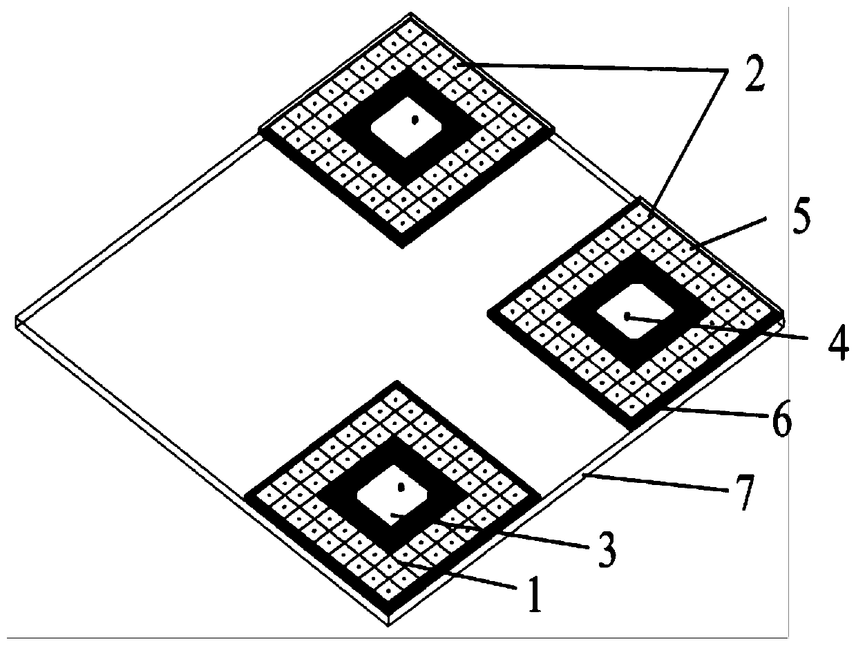
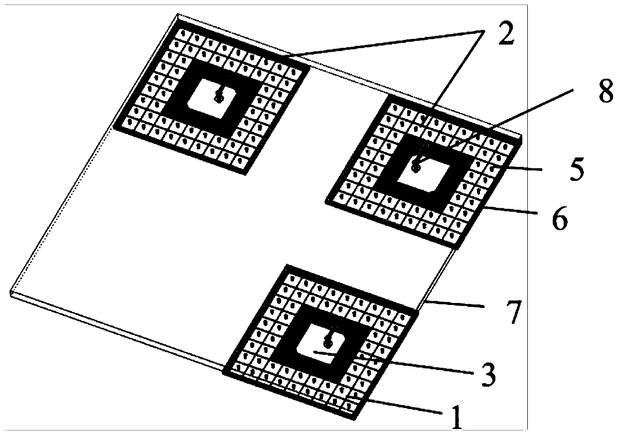
[0023] figure 1 It is the front structure diagram of the circularly polarized patch antenna with one transmission and two receptions of the present invention; figure 2 It is the structure diagram of the back side of the circularly polarized patch antenna with one sending and two receiving in the present invention; figure 1 The front view of the above is a schematic view viewed from the upper part of the one-transmission-two-retraction circularly polarized integrated antenna to the upper end surface of the one-transmission-two-retraction circularly polarized integrated antenna, figure 2 The rear view is a schematic view viewed from the lower part of the one-throw, two-retract circularly polarized integrated antenna to the lower end surface of the one-pitch, two-retract circularly polarized integrated antenna.

[0024] The circularly polarized integrated antenna of the present invention includes a circularly polarized patch antenna unit and a printed circuit board 7, and the ...

Embodiment 2

[0036] In this embodiment, a specific structural layout of a circularly polarized integrated antenna with one transmission and two receptions is provided. The three circularly polarized patch antenna units independently correspond to a square microstrip plate 6 . The transmitting antenna unit 1 is located at the lower left corner of the rectangular printed circuit board 7, and the two receiving antenna units 2 are respectively located at the upper right corner and the lower right corner of the rectangular printed circuit board 7, and the transmitting antenna unit 1 at the lower left corner is The structure of the receiving antenna unit 2 in the upper right corner is exactly the same, and it belongs to the same polarization setting; the transmitting antenna unit 1 in the lower left corner and the receiving antenna unit 2 in the lower right corner are formed by the vertical middle line of the rectangular printed circuit board 7 It is a mirror image symmetry relationship, which b...


PUM


Abstract

The invention discloses a one-emission-two-receiving circularly-polarized integrated antenna. The one-emission-two-receiving circularly-polarized integrated antenna comprises a circularly-polarized patch antenna unit and a printed circuit board, wherein the circularly-polarized patch antenna unit and a feeding structure are integrated onto the printed circuit board, the circularly-polarized patchantenna comprises a microstrip plate, an antenna radiator and a metal post probe, the antenna radiator is arranged on an upper surface of the microstrip plate, the metal post probe vertically penetrates through the microstrip plate and the printed circuit board, two ends of the metal post probe are respectively connected with the antenna radiator on the upper surface of the microstrip plate and amicrostrip line on a lower surface of the printed circuit board, and a plurality of electromagnetic bandgap structure units are arranged at an outer side of the antenna radiator and are annularly distributed. By the one-emission-two-receiving circularly-polarized integrated antenna, the isolation between the antenna units can be effectively, the directional diagram, the shaft ratio and the gain performance of the antenna units are improved, and the integration of the antenna and a circuit and a component on the printed circuit board is facilitated.

Description

technical field [0001] The invention relates to the technical field of antennas, in particular to a circularly polarized integrated antenna with one transmission and two receptions. Background technique [0002] In order to meet the application requirements of short-range life detection, through-wall detection, and packing box detection, short-range radar detection products have been promoted and applied. Circularly polarized waves can detect the electromagnetic signal characteristics of vertically polarized waves and horizontally polarized waves. Therefore, it is more advantageous for short-range detection radars to use circularly polarized antennas. A circularly polarized antenna with one send and two receive is integrated on the printed board, which can well meet the needs of short-distance electromagnetic transmission and reception. [0003] However, under the influence of ensuring system integration and miniaturization, the transmitting and receiving antennas are not o...

Claims


Application Information

Patent Timeline
Patent Type & Authority Applications(China)
IPC IPC(8): H01Q1/38H01Q1/50H01Q1/52H01Q21/00H01Q21/24H01Q21/28
CPCH01Q1/38H01Q1/50H01Q1/521H01Q21/0006H01Q21/24H01Q21/28
Inventor 陈谦万应禄张小林金谋平马强戴跃飞
Owner CHINA ELECTRONIC TECH GRP CORP NO 38 RES INST
Why Eureka
Try Eureka