Breaking device and inverter system
A breaking device and breaking unit technology, applied in the direction of automatic disconnection emergency protection device, circuit device, emergency protection circuit device, etc., can solve the problem of shortening the service life of the fuse, affecting the reliability of the breaking device, and low reliability of the breaking device problem, to achieve the effect of alleviating the fever phenomenon, alleviating the fever phenomenon, and high reliability
- Summary
- Abstract
- Description
- Claims
- Application Information
AI Technical Summary
Problems solved by technology
Method used
Image

Examples
example 1
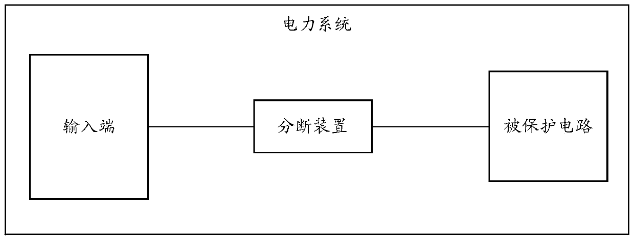
[0095] see Image 6 , a breaking device provided in the embodiment of the present application. The breaking device is connected in series between the DC input terminal and the protected circuit, and when the protected circuit fails, the breaking device disconnects the electrical connection between the DC input terminal and the protected circuit.
[0096] Image 6 Disconnecting devices shown include fuses, current limiting resistors, relays and controllers. Among them, after the fuse and the current limiting resistor are connected in series, they are connected in parallel with the relay; the controller is used to control the pull-in or disconnection of the relay.
[0097] Image 6 The working principle of the shown breaking device is as follows: During normal operation, the controller controls the relay to pull in, and the current is shunted through the two branches of the fuse and the current limiting resistor series branch and the relay branch. The impedance of the resist...
example 2
[0106] see Figure 7 , a breaking device provided in the embodiment of the present application. The breaking device is connected in series between the DC input terminal and the protected circuit, and when the protected circuit fails, the breaking device disconnects the electrical connection between the DC input terminal and the protected circuit.
[0107] Figure 7 The disconnecting devices shown include fuses, diodes, relays and controllers. Among them, after the fuse and the diode are connected in series, they are connected in parallel with the relay; the controller is used to control the pull-in or disconnection of the relay.
[0108] Figure 7 The working principle of the shown breaking device is as follows: During normal operation, the controller controls the relay to pull in, and the current is shunted through the fuse and the diode series branch and the two branches of the relay branch. The conduction voltage drop acts on the relay branch. At this time, most of the ...
example 3
[0117] see Figure 8 , is a breaking device provided in the embodiment of this application. The breaking device is connected in series between the DC input terminal and the protected circuit. When the protected circuit fails, the breaking device disconnects the electrical connection between the DC input terminal and the protected circuit.
[0118] Figure 8 The breaking device shown includes a fuse, an oxide film removal circuit, a first relay, a controller, and a first current limiting resistor. The oxide film removal circuit is composed of a second relay and a second current limiting resistor connected in parallel, and the second relay is a normally closed relay. Wherein, the fuse, the first current limiting resistor, and the oxide film removal circuit are connected in parallel with the first relay after being connected in series; the controller is used to control the first relay to be turned on or off, and the second relay to be turned on or off.
[0119] Wherein, the de...
PUM
 Abstract
Description
Claims
Application Information
 - R&D
- Intellectual Property
- Life Sciences
- Materials
- Tech Scout
- Unparalleled Data Quality
- Higher Quality Content
- 60% Fewer Hallucinations
Browse by: Latest US Patents, China's latest patents, Technical Efficacy Thesaurus, Application Domain, Technology Topic, Popular Technical Reports.
© 2025 PatSnap. All rights reserved.Legal|Privacy policy|Modern Slavery Act Transparency Statement|Sitemap|About US| Contact US: help@patsnap.com