Ultrasonic cutter handle

A tool holder and ultrasonic technology, applied in the field of milling processing, can solve the problem of not meeting the requirements of material processing, and achieve the effect of improving processing efficiency and processing quality, increasing excitation frequency and ensuring dynamic balance.

Active Publication Date: 2019-07-26
SHANGHAI INST OF TECH
View PDF7 Cites 8 Cited by
  • Summary
  • Abstract
  • Description
  • Claims
  • Application Information

AI Technical Summary

Problems solved by technology

[0004] However, with the deepening of research on ultrasonic processing technology and the development of ultrasonic equipment, s

Method used


Image

  • Ultrasonic cutter handle
  • Ultrasonic cutter handle
  • Ultrasonic cutter handle

Examples


Embodiment Construction

[0039] The ultrasonic knife holder proposed by the present invention will be described in further detail below in conjunction with the accompanying drawings and specific embodiments. Advantages and features of the present invention will be apparent from the following description and claims.

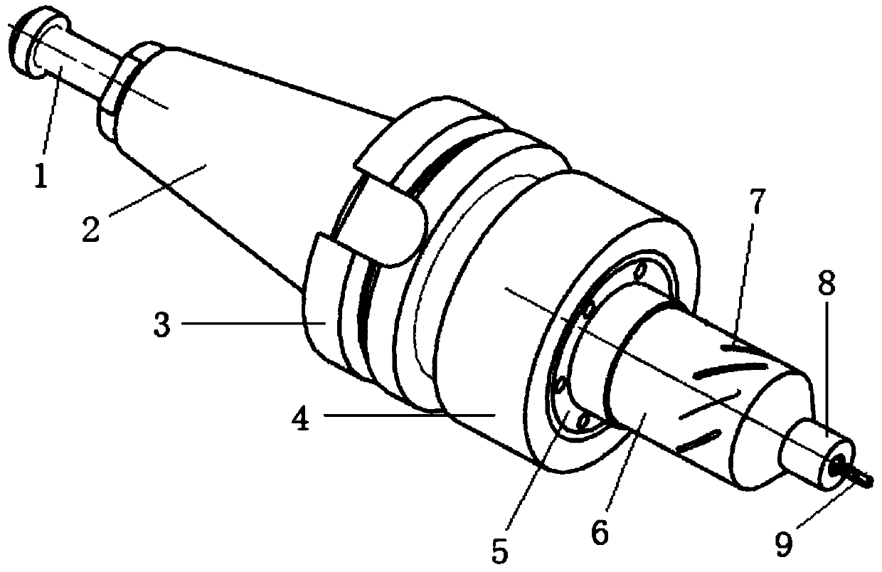
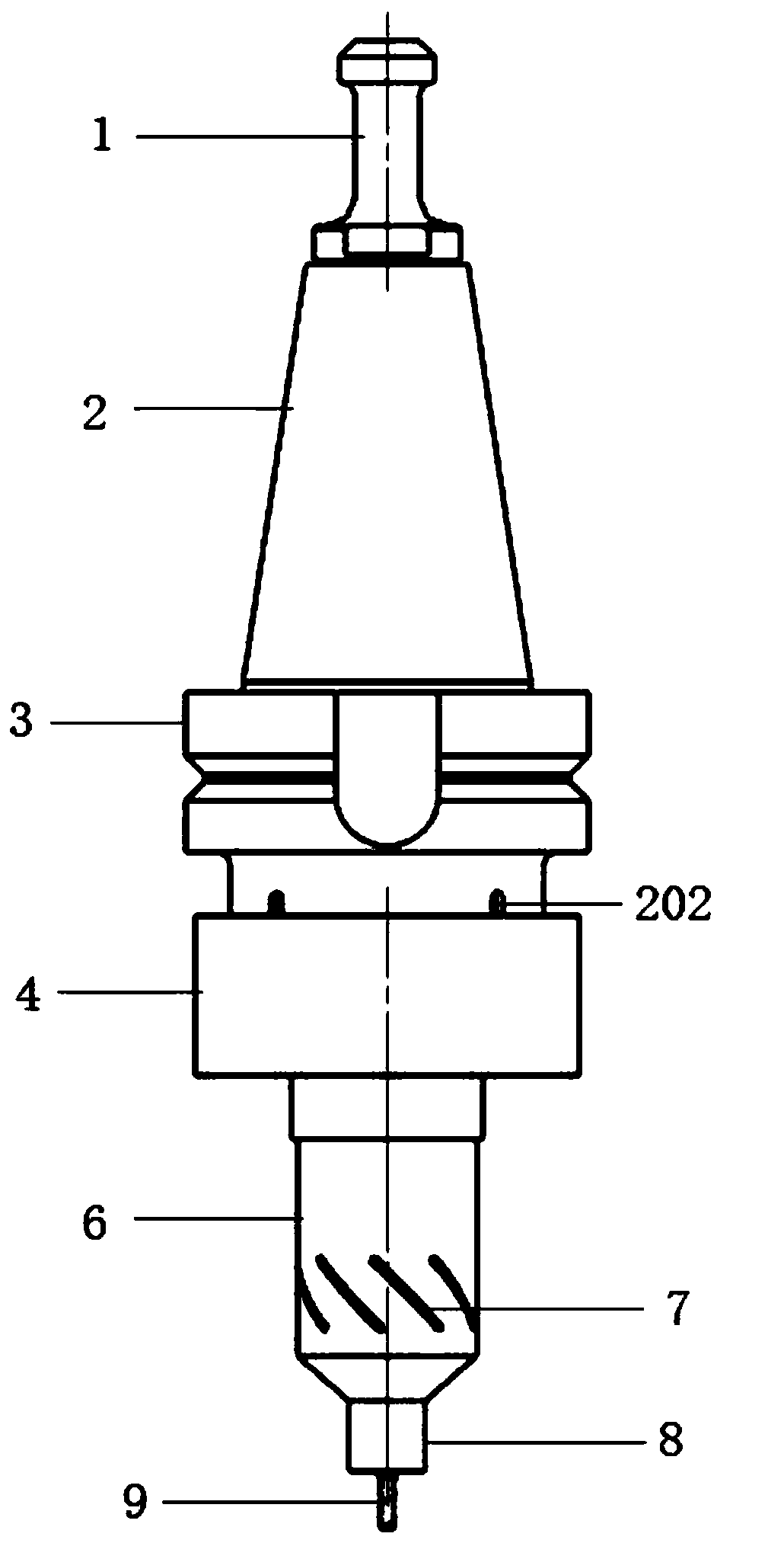
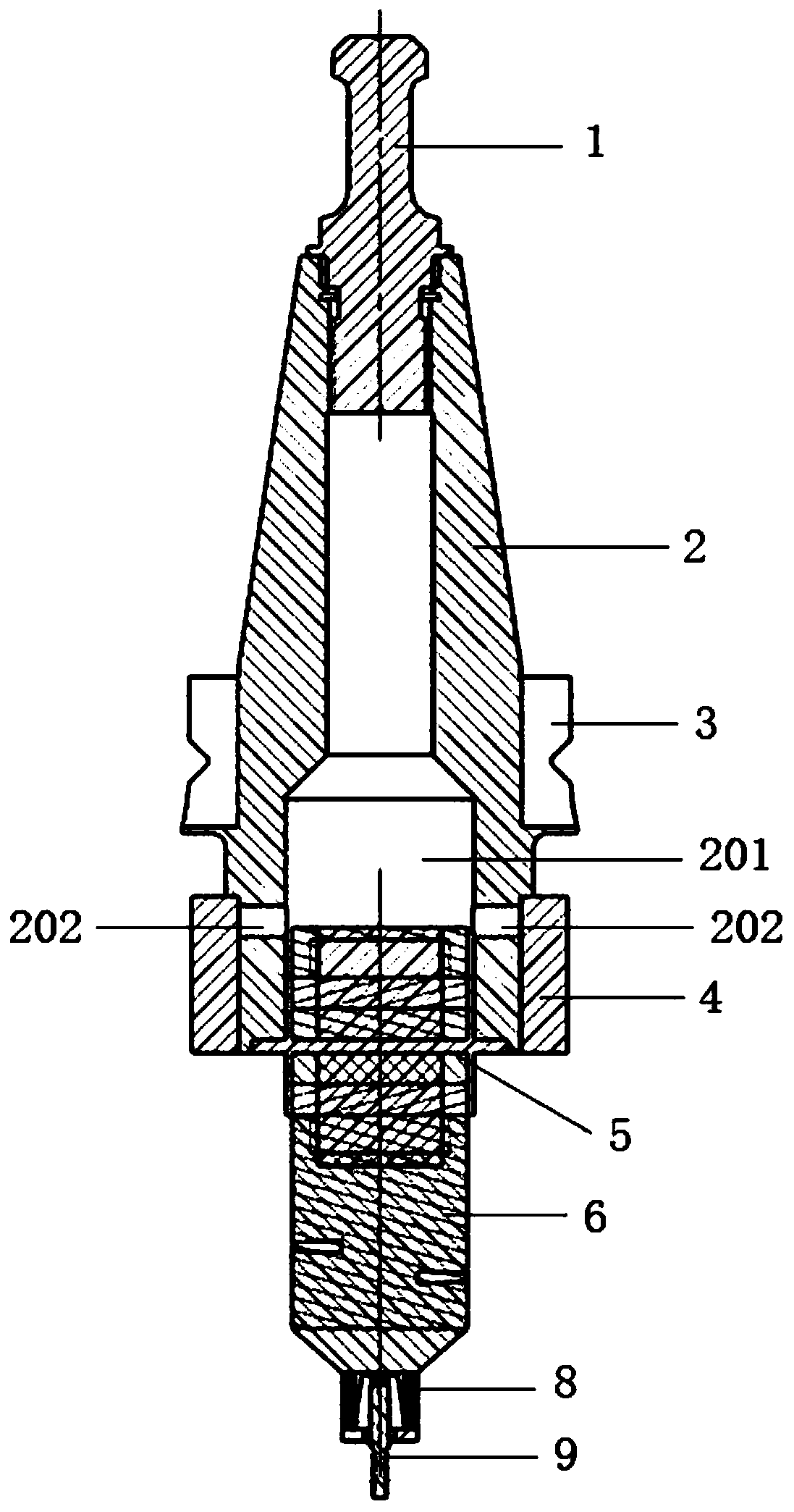
[0040] Such as figure 1 As shown, the ultrasonic knife handle provided by the present invention includes: pull stud 1; knife handle 2, the front end of knife handle 2 is detachably connected with pull stud 1, and the end of knife handle 2 is provided with cavity 201, and the opening of cavity 201 There is a depression with a diameter smaller than the outer diameter of the end of the handle 2; the flange 5 includes a first stud 501, a second stud 505, a first cylinder 502, a second cylinder 504 and a disc 503 ; The first stud 501 is fixed at the center of the upper surface of the disc 503, the first cylinder 502 is sleeved outside the first stud 501 and is fixedly connected with the upper...


PUM

PropertyMeasurementUnit
Lengthaaaaaaaaaa
Widthaaaaaaaaaa
Depthaaaaaaaaaa

Abstract

The invention discloses an ultrasonic cutter handle which comprises a blind rivet, a cutter handle, a flange plate and an ultrasonic milling device. The front end of the cutter handle is detachably connected with the blind rivet; the flange plate adopts a symmetric design and is fixedly connected with the tail end of the cutter handle; the ultrasonic milling device comprises a first piezoelectricceramic assembly, a second piezoelectric ceramic assembly, a third piezoelectric ceramic assembly, a fourth piezoelectric ceramic assembly, an amplitude-change pole and a chuck; the first piezoelectric ceramic assembly and the second piezoelectric ceramic assembly are symmetrical with respect to the flange plate; the amplitude-change pole comprises a cylindrical section and a conical section; oneend of the cylindrical section supports the third piezoelectric ceramic assembly and the fourth piezoelectric ceramic assembly; the other end of the cylindrical section is fixedly connected with the bottom end of the conical section; and a circle of spiral groove is uniformly formed in the surface of the cylindrical section. The flange plate with the symmetric design is adopted, and one circle ofspiral groove is arranged on the cylindrical section of the amplitude-change pole, so that longitudinal and torsional two-dimensional ultrasonic vibration can be output at the same time; and in addition, longitudinal and torsional nodes coincide in positions on the flange plate, so that the excitation frequency of the ultrasonic milling device and the ultrasonic wave transmission efficiency are improved.

Description

technical field [0001] The invention belongs to the technical field of milling, and in particular relates to an ultrasonic tool holder. Background technique [0002] With the continuous improvement of modern technology and industry's requirements for materials, especially in the fields of aerospace, chemical industry, military, machinery, electronic appliances and precision manufacturing, in addition to some special properties, materials must also have excellent comprehensive properties. However, these materials often have processing difficulties such as high strength, high hardness, high brittleness and anisotropy, making it difficult for traditional milling processes to achieve efficient and high-quality milling. [0003] Compared with traditional mechanical processing, ultrasonic vibration cutting can not only reduce the cutting force and cutting heat effect, but also greatly reduce the surface roughness of the processed workpiece, improve the processing accuracy and prol...

Claims


Application Information

Patent Timeline
IPC IPC(8): B23Q3/12B23Q11/10B06B1/06
CPCB06B1/06B23Q3/12B23Q11/10
Inventor 聂文忠马亚健陆建明陈晓东
Owner SHANGHAI INST OF TECH
Why Eureka
Try Eureka