Monocular vision plane distance measuring method free of photo-control

A technology of plane distance and measurement method, applied in measurement devices, instruments, and optical devices, etc., can solve the problems of difficult layout of image control points, measurement accuracy, sensitivity to quantity and distribution conditions, and lack of universality.

Active Publication Date: 2019-07-26
HOHAI UNIV
View PDF2 Cites 19 Cited by
  • Summary
  • Abstract
  • Description
  • Claims
  • Application Information

AI Technical Summary

Problems solved by technology

However, due to the lack of depth information in the imaging process of a single image, the mapping relationship between the three-dimensional world coordinates and the two-dimensional image coordinates is irreversible. Usually, additional coplanar constraints are required to establish the image plane and object plane described by the homography matrix. Reversible coordinate transformation relationship between planes
The main method used is the direct linear transformation method based on point correspondence to solve the homography matrix, that is, use more than 4 image control points in the plane to be measured to solve the homography matrix, and then use the homography matrix to solve the homography matrix. The coordinates of the image point in the object plane, and then calculate the distance between two points; its measurement accuracy is sensitive to factors such as the accuracy, quantity and distribution conditions of the image control point, and the image control point in the complex measurement environment such as the water surface The layout is more difficult, which often limits the use of this method
Other methods use the

Method used


Image

  • Monocular vision plane distance measuring method free of photo-control
  • Monocular vision plane distance measuring method free of photo-control
  • Monocular vision plane distance measuring method free of photo-control

Examples


Embodiment Construction

[0081] This specific embodiment discloses a monocular visual plane distance measurement method without image control, including:

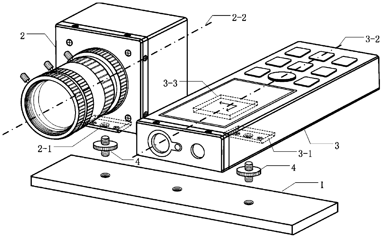
[0082] Measurement system integration stage: the camera and laser rangefinder are fixedly connected to form a direct directional vision measurement system;

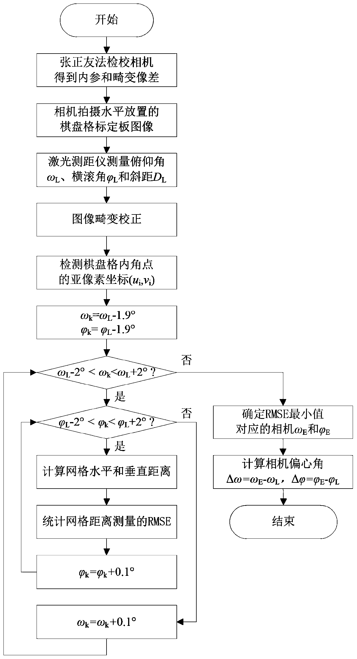
[0083] Measurement system calibration stage: integrated calibration of the measurement system, determination of camera internal parameters, distortion aberration, and eccentricity angle between the camera and the laser rangefinder, correction of nonlinear distortion of the camera, measured elevation and attitude;

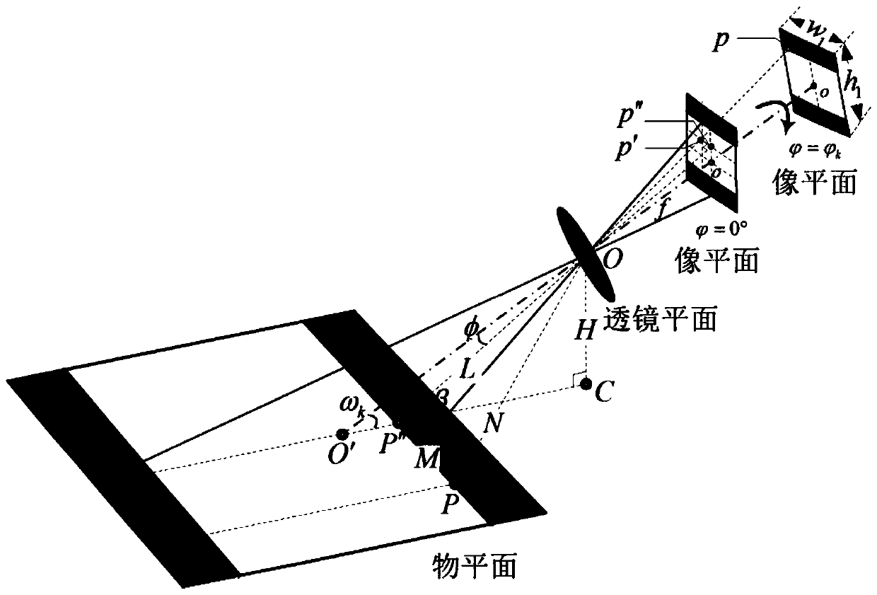
[0084] Plane distance measurement stage: Based on the central projection imaging principle that the image point, optical center and object point are collinear under the oblique viewing angle of the camera, the "image point-distance" transformation relationship between the image plane and the object plane is established, and finally image-free control is realized Monocular visual pla...


PUM


Abstract

The invention discloses a monocular vision plane distance measuring method free of photo-control. The method comprises the following steps of a measurement system integration stage: fixedly connectinga camera and a laser range finder to form a direct oriented vision measurement system; a measurement system calibration stage: performing integrated calibration on the measurement system to determinecamera internal parameters, distortion aberrations and an eccentric angle between the camera and the laser range finder, and correcting the nonlinear distortion, measured elevation and attitude of the camera; and a plane distance measurement stage: establishing an "image-distance" transformation relationship between the image plane and the object plane based on a central projection imaging principle of the collinearity of the image point, optic center and object point of the camera in an oblique angle of view, and finally realizing the monocular vision plane distance measurement free of photo-control. The method provided by the invention has low hardware cost and operational complexity, greatly reduces the workload in the field by completing the measuring point layout in a few minutes with no need to arrange photo-control points on the plane to be tested, and has universality without depending on the prior knowledge in the scene.

Description

technical field [0001] The invention relates to the field of plane distance measurement, in particular to an image control-free monocular vision plane distance measurement method. Background technique [0002] Visual measurement is a non-contact measurement technology formed with the development of computer vision technology. Compared with traditional measurement methods, it has the advantages of large measurement range, more measurement information, less restriction by the working environment, and no interference with the measurement object. According to the number of cameras used, the visual measurement system can be divided into monocular vision measurement, binocular vision measurement, multi-eye vision measurement and structured light vision measurement. Among them, the technology of using a single image captured by a single camera to measure the geometric size or spatial position of an object is called monocular vision measurement in the field of machine vision. Due t...

Claims


Application Information

Patent Timeline
IPC IPC(8): G01B11/02
CPCG01B11/002G01B11/022
Inventor 张振周扬夏颖刘海韵嵇阳王慧斌
Owner HOHAI UNIV
Why Eureka
Try Eureka