Simulation device and test method for oscillating heat transfer performance of cold oil duct in piston

A heat transfer performance and simulation device technology, which is applied in the direction of material thermal development, material thermal conductivity, etc., can solve the problems of evaluating the cooling effect of the internal cooling oil chamber, simplifying the model, increasing the experimental period and cost, etc.

Inactive Publication Date: 2019-07-26
KUNMING UNIV OF SCI & TECH
View PDF6 Cites 2 Cited by
  • Summary
  • Abstract
  • Description
  • Claims
  • Application Information

AI Technical Summary

Problems solved by technology

However, the simulation calculation of the flow and heat transfer in the oil channel is a simplification of the cooling oil chamber in the piston. The accuracy of the simplified model is difficult to guarantee, and a large number of experimental verifications are required, which increases the experimental cycle and experimental cost.
The development of the oscillating flow heat transfer simulation experiment device is to drive the engine crank connecting rod mechanism and the long piston to move through the motor, use high-temperature gas to heat the piston, and finally evaluate the cooling effect of the oil chamber through the outlet oil temperature, but such The device can only indirectly measure the heat transfer effect of the oil chamber through the outlet oil temperature, and cannot directly observe the vibration and heat transfer of the oil in the internal cooling oil chamber of the piston and the uneven heating during heating, and cannot evaluate the internal cooling oil chamber through the heat transfer coefficient cooling effect

Method used


Image

  • Simulation device and test method for oscillating heat transfer performance of cold oil duct in piston
  • Simulation device and test method for oscillating heat transfer performance of cold oil duct in piston
  • Simulation device and test method for oscillating heat transfer performance of cold oil duct in piston

Examples


Embodiment 1

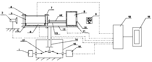
[0031] Embodiment 1: as Figure 1-4 As shown, a simulation device for oscillating heat transfer performance of the internal cooling oil channel of the piston, including a main body oscillating device, a rectangular cavity heating device, a cooling liquid supply and collection device, high-speed photography equipment 2, bolts 7, an installation platform 12, and a control box 18 , computer 19;

[0032] The installation platform 12 is installed on the upper side of the main body oscillating device, and is connected with the main body oscillating device. The rectangular cavity heating device is installed and fixed on one end of the installation platform 12 by bolts 7. The high-speed photography equipment 2 is used to photograph the cooling in the rectangular cavity heating device. In the case of liquid oscillation, the cooling liquid supply and collection device is installed and fixed on the other end of the installation platform 12, and the control box 18 is connected to the comp...


PUM


Abstract

The invention relates to a simulation device and test method for oscillating heat transfer performance of a cold oil duct in a piston.The simulation device for oscillating heat transfer performance ofthe cold oil duct in the piston comprises a main body oscillating device, a rectangular cavity heating device, a coolant supply collecting device, a high-speed photographic device, bolts, a mountingplatform, a control box, and a computer;the mounting platform is mounted on the upper side of the main body oscillating device and connected with the main body oscillating device,the rectangular cavity heating device is fixed to one end of the upper surface of the mounting platform through the bolts, the coolant supply collecting device is fixedly mounted on the other end of the upper surface of the mounting platform,the control box is connected with the computer, the main body oscillating device, the rectangular cavity heating device, the coolant supply collecting device, and the high-speed photographic device through wires for data transmission. According to the simulation device and test method for oscillating heat transfer performance of the cold oil duct in the piston, the oscillatingworking condition under the actual working condition of the piston is dynamically simulated, the oscillating flow characteristic of a coolantcan be intuitively observed by using the high-speed camera, at the same time the wall surface heat transfer coefficient can be calculated, and the oscillating heat transfer performance of the cold oil duct in the piston is further analyzed.

Description

technical field [0001] The invention relates to a simulation device and a test method for the oscillating heat transfer performance of a piston internal cooling oil channel, and belongs to the technical field of internal combustion engine piston tests. [0002] technical background [0003] As an important component of the combustion chamber of a diesel engine, the piston has an extremely harsh working environment. It must not only bear the high-temperature heat load of the instantaneous gas change, but also bear the gas pressure and the mechanical load imposed by the outside during the reciprocating motion. The head of the piston is directly in contact with the high-temperature gas, so that the maximum temperature of the piston has reached about 400°C. High gas temperature not only increases the thermal load of the piston, but also reduces the mechanical properties of the piston material, thereby reducing the thermal fatigue life of the piston. Therefore, reducing the therm...

Claims


Application Information

Patent Timeline
Patent Type & Authority Applications(China)
IPC IPC(8): G01N25/18G01N25/20
CPCG01N25/18G01N25/20
Inventor 邓晰文陈浩谢光义雷基林
Owner KUNMING UNIV OF SCI & TECH
Why Eureka
Try Eureka