Supercharge Your Innovation With Domain-Expert AI Agents!

Ammonia gas generation device

An ammonia gas generation and air intake pipe technology, which is applied in gas treatment, ammonia compounds, climate sustainability, etc., can solve the problems of insufficient mixing of urea solution and low ammonia gas production.

Pending Publication Date: 2019-07-30
湖南省约伯能源科技有限公司
View PDF5 Cites 0 Cited by
  • Summary
  • Abstract
  • Description
  • Claims
  • Application Information

AI Technical Summary

Problems solved by technology

[0005] In order to solve the above-mentioned problems in the prior art, that is, in order to solve the problem of insufficient mixing of high-temperature flue gas and atomized urea solution and low ammonia production in the ammonia generating device of the existing flue gas denitrification system, the present invention provides A kind of ammonia generating device, the ammonia generating device comprises a cylindrical housing with an inner cavity, and the housing is provided with a liquid inlet pipe, an air inlet pipe, a liquid outlet and an air outlet; the liquid inlet pipe is provided with In the middle position of the top of the housing, the part of the liquid inlet pipe located in the housing is provided with a spraying member, and the spraying member is used to spray the ammonia making stock solution into the housing; the inlet pipe is used for For transporting high-temperature flue gas into the housing; the liquid outlet and the gas outlet are both arranged at the bottom of the housing, and are respectively used to discharge the liquid product and gas product of the ammonia production reaction; The inner wall is provided with a spiral guide member extending from top to bottom

Method used


Image

  • Ammonia gas generation device
  • Ammonia gas generation device
  • Ammonia gas generation device

Examples


Embodiment Construction

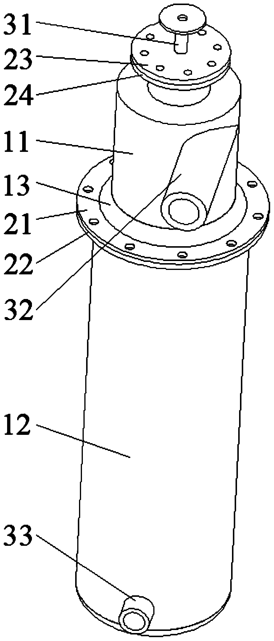
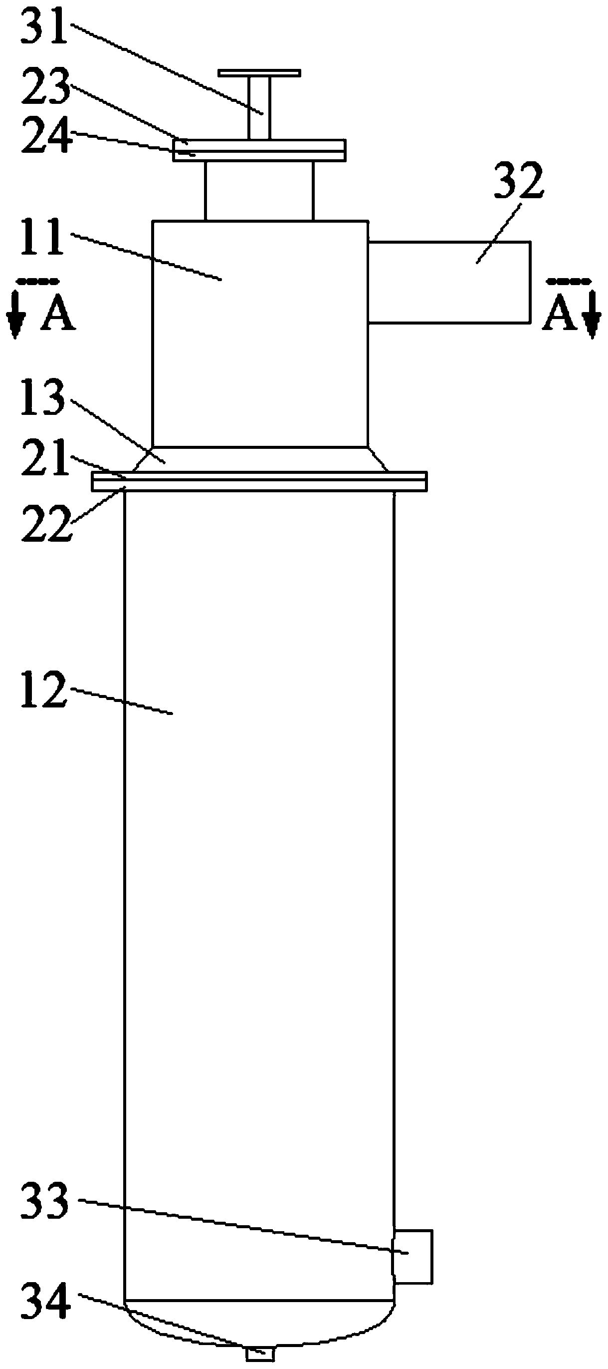
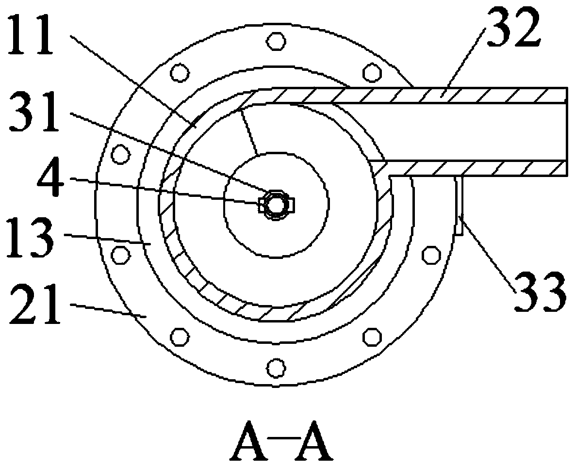
[0024] Preferred embodiments of the present invention are described below with reference to the accompanying drawings. Those skilled in the art should understand that these embodiments are only used to explain the technical principles of the present invention, and are not intended to limit the protection scope of the present invention. For example, although the housing of the ammonia generator of the present invention includes two upper and lower housings with different diameters, those skilled in the art can make adjustments to it according to needs in order to adapt to specific applications, such as the present invention The shell of the ammonia gas generating device can be an upper shell and a lower shell with two sections of the same diameter, or an integral shell with a cylindrical inner cavity. Obviously, the adjusted technical solution will still fall into the protection scope of the present invention.

[0025] It should be noted that, in the description of the present...


PUM


Abstract

The invention relates to the technical field of ammonia gas preparation, in particular to an ammonia gas generation device. The device aims at solving the problems of insufficient mixing of high-temperature flue gas and an atomized urea solution and low ammonia gas yield in the ammonia gas generation device of an existing flue gas denitrification system. The ammonia gas generation device comprisesa cylindrical shell with an inner cavity, wherein the shell is provided with a liquid inlet pipe, an air inlet pipe, a liquid outlet and an air outlet; the liquid inlet pipe is arranged at the middleposition of the top of the shell and extends downwards; the liquid inlet pipe is provided with a spraying assembly used for spraying stock solution for ammonia gas preparation into the shell; the airinlet pipe is used for conveying high-temperature flue gas into the shell; the liquid outlet and the air outlet are arranged at the bottom of the shell and are used for discharging liquid products and gas products of the ammonia gas preparation reaction respectively; and the inner wall of the shell is provided with a spiral guiding assembly extending downwards from top to form a rotary airflow inthe shell. The rotary airflow fully mixes the atomized liquid with the high-temperature gas so as to improve the yield of the ammonia gas.

Description

technical field [0001] The invention relates to the technical field of ammonia gas preparation, and specifically provides an ammonia gas generating device. Background technique [0002] The flue gas emitted by thermal power plants, smelters, and industrial boilers contains a large amount of NOx, which is the main pollutant that produces acid rain in the atmosphere. At present, the most mature flue gas denitrification technology is selective catalytic reduction (SCR), whose principle is to use ammonia gas to reduce NOx in flue gas to N 2 and H 2 O. Usually, in the flue gas denitrification system, the concentrated ammonia water is added to the ammonia gas generating device to be heated to generate ammonia gas, and the generated ammonia gas is mixed with the flue gas to reduce the NOx in the flue gas. However, it is inconvenient to transport concentrated ammonia water as a raw material for the preparation of ammonia gas, and there are greater safety risks. [0003] In view ...

Claims


Application Information

Patent Timeline
Patent Type & Authority Applications(China)
IPC IPC(8): C01C1/02B01D53/86B01D53/56
CPCC01C1/026B01D53/8631B01D2251/2062B01D2258/0283Y02P20/50
Inventor 戴旭建
Owner 湖南省约伯能源科技有限公司
Features
  • R&D
  • Intellectual Property
  • Life Sciences
  • Materials
  • Tech Scout
  • Unparalleled Data Quality
  • Higher Quality Content
  • 60% Fewer Hallucinations
Learn More